-
Notifications
You must be signed in to change notification settings - Fork 46
Contrib. Project: Encap Decap
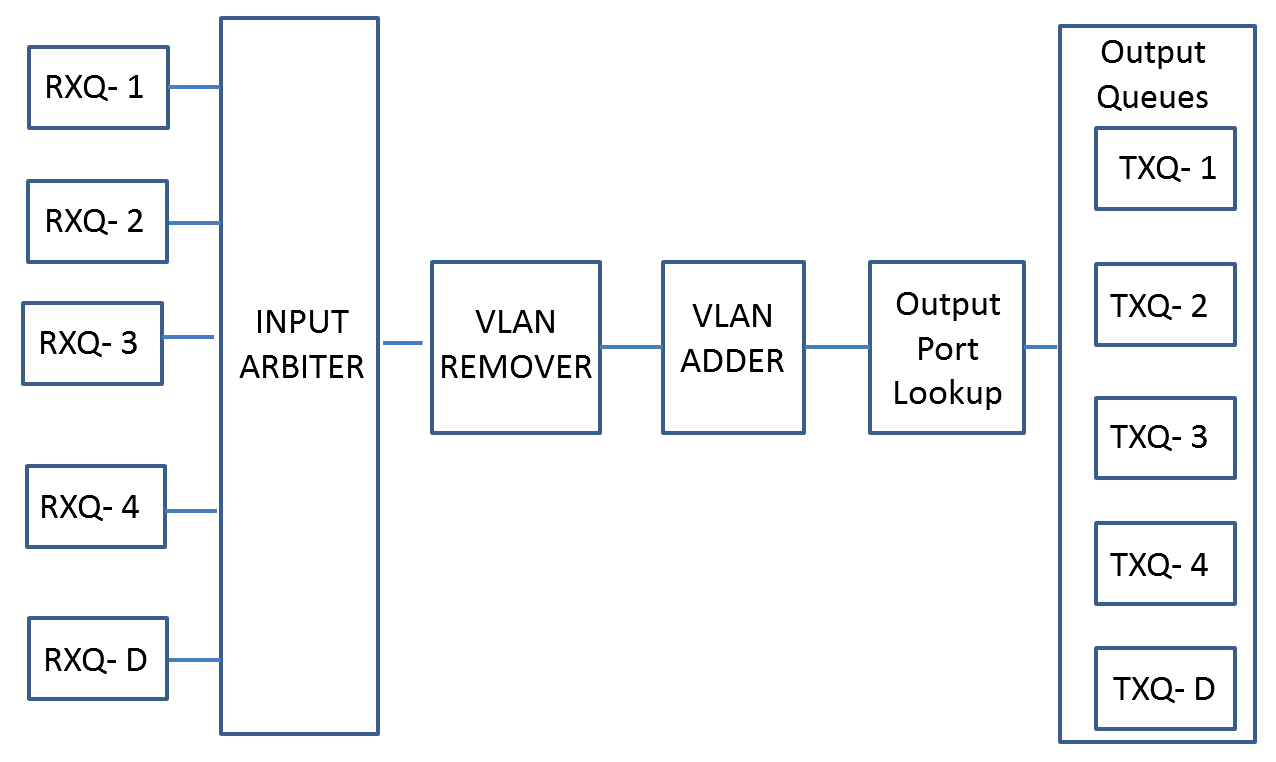
VLAN Adder and Remover are added in the standard NetFPGA reference pipeline as shown below. Based on the physical interface in which the packet enters, a VLAN tag may be added or removed.

All the packets sent through the nf2 or nf3 physical interface will be appended with VLAN tags. The vlan-tagged packets can come out through the nf0 or nf1 (or both) physical interface based on the register configuration set in the nic_output_port_lookup (v4). Currently the tag that is inserted into the packets can be configured through the register.
All the packets received through the nf0 or nf1 physical interface will be checked for VLAN tags. If they are vlan-tagged, the vlan tags will be removed and the resulting packets will be sent through nf2 or nf3 (or both) physical interface based on the register configuration set in the nic_output_port_lookup (v4).
This section describes the process to generate a working bitfile for the encap-decap project. This project was implemented with Vivado 2014.4 tools.
cd $SUME_FOLDER
make
cd $NF_DESIGN_DIR
cp vlan.patch $SUME_FOLDER
cd $SUME_FOLDER
patch -p1 < vlan.patch
cd $NF_DESIGN_DIR
make
patch -R -p1 < vlan.patch
The simulation and hardware test
.
├── both_vlan_demuxing
├── both_vlan_muxing
├── connections
├── global
└── reg_defines_vlan_tags.py
VLAN packets can be pushed through nf0 or nf1. VLAN tags are stripped along the pipeline and the packets are sent to both nf2 and nf3. The direction of the desired output can be controlled in the output port lookup module.
ordinary packets are pushed through nf2 or nf3 interface. VLAN tags are added along the pipeline and the VLAN tagged packets are sent to both nf0 and nf1. The direction of the desired output can be controlled in the output port lookup module.
The connections folder includes the way the physical interfaces are connected. In the current case, I am using a quad port NIC to do the tests. But the connection file can be modified to do the same tests on a dual port NIC.
./nftest.py sim --major {major_name} --minor {minor_name} --gui
This project uses the uses the NetFPGA HW infrastructure to generate packets. We use custom python scripts to verify if the packets sent and received match.
Note: If you use a dual port nic, you need to make modifications (interfaces to be tapped) to the test.py file.
cd $NF_DESIGN_DIR/hwtest
make all
Below is the dump of the make all
root@my-machine:~/git/NetFPGA-SUME-dev/contrib-projects/vlan_tags/hwtest# make all
make clean
make[1]: Entering directory `/root/git/NetFPGA-SUME-dev/contrib-projects/vlan_tags/hwtest'
rm -rf both_vlan_muxing both_vlan_demuxing
rm -f *.pyc *.dat
make[1]: Leaving directory `/root/git/NetFPGA-SUME-dev/contrib-projects/vlan_tags/hwtest'
python test.py
(1, function both_vlan_muxing at 0x2abe884b80c8)
(2, function both_vlan_demuxing at 0x2abe884b8140)
Enter a file name:
You can enter either 1 or 2 to run vlan_muxing test or vlan_demuxing test.
In the final output, you should see that you receive the following.
### SUCCESS : Files Are Identical! ###
If not the test has not succeeded. You will receive a warning.