Tool for automated world-based analysis of wearable eye tracker data. gazeMapper is an open-source tool for automated mapping and processing of eye-tracking data to enable automated world-based analysis. gazeMapper can:
- Transform head-centered data to one or multiple planar surfaces in the world.
- Synchronize recordings from multiple participants, and external cameras.
- Determine data quality measures, e.g., accuracy and precision using glassesValidator (Niehorster et al., 2023).
If you use this tool or any of the code in this repository, please cite:
Niehorster, D.C., Hessels, R.S., Nyström, M., Benjamins, J.S. and Hooge, I.T.C. (submitted). gazeMapper: A tool for automated world-based analysis of gaze data from one or multiple wearable eye trackers. Manuscript submitted for publication, 2024 (BibTeX)
If you use the functionality for automatic determining the data quality (accuracy and precision) of wearable eye tracker recordings, please additionally cite:
Niehorster, D.C., Hessels, R.S., Benjamins, J.S., Nyström, M. and Hooge, I.T.C. (2023). GlassesValidator:
A data quality tool for eye tracking glasses. Behavior Research Methods. doi: 10.3758/s13428-023-02105-5 (BibTeX)
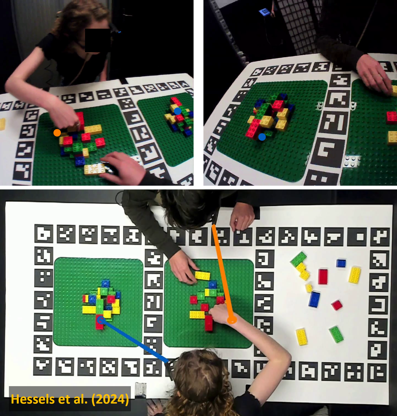 Example where gazeMapper has been used to map head-centered gaze from two head-worn eye tracker recordings to synchronized world-centered
gaze data of the pair, drawn on an overview video recording with an additional external camera. From Hessels, R.S., Iwabuchi, T., Niehorster, D.C., Funawatari, R., Benjamins, J.S., Kawakami, S.; Nyström, M., Suda, M., Hooge, I.T.C., Sumiya, M., Heijnen, J., Teunisse, M. & Senju, A. (submitted). Gaze behavior in face-to-face interaction: A cross-cultural investigation between Japan and the Netherlands. Manuscript submitted for publication, 2024
GazeMapper is available from https://github.com/dcnieho/gazeMapper, and supports Python 3.10 and 3.11 on Windows, MacOS and Linux (newer versions of Python should work fine but are not tested).
For Windows users who wish to use the gazeMapper GUI, the easiest way to acquire gazeMapper is to download a standalone executable. The standalone executable is not available for MacOS or Linux. Complete installation instruction for MacOS and Linux users are available below.
For users on Windows, Mac or Linux who wish to use gazeMapper in their Python code, the easiest way to acquire
gazeMapper is to install it directly into your Python distribution using the command
python -m pip install gazeMapper.
If you run into problems on MacOS to install the imgui_bundle package, you can
try to install it first with the command SYSTEM_VERSION_COMPAT=0 pip install --only-binary=:all: imgui_bundle. Note that this repository is pip-installable as well:
python -m pip install git+https://github.com/dcnieho/gazeMapper.git#egg=gazeMapper. NB: on some platforms you may have
to replace python with python3 in the above command lines.
Once pip-installed in your Python distribution, there are three ways to run the GUI on any of the supported operating systems:
- Directly in the terminal of your operating system, type
gazeMapperand run it (NB: this does not appear to work in Anaconda environments, use one of the below methods for those). - Open a Python console. From such a console, running the GUI requires only the following two lines of code:
import gazeMapper
gazeMapper.GUI.run()
- If you run the gazeMapper's GUI from a script, make sure to wrap your script in
if __name__=="__main__". This is required for correct operation from a script because the GUI uses multiprocessing functionality. Do as follows:if __name__=="__main__": import gazeMapper gazeMapper.GUI.run()
Installing and running gazeMapper on a Mac will involve some use of the terminal. In this section we will show you step by step how to install, and then what to do every time you want to run gazeMapper.
Note that it is critical on MacOS that gazeMapper is installed natively, and not under Rosetta or Parallels. That will lead to an error when importing the polars package, and other unfixable errors.
- To acquire and manage Python, install Anaconda by following these instructions. Additional notes: a. Choose the graphical installer. b. When clicking the installer link provided in these instructions, you may first be shown a user registration page. You can click "skip registration" there to directly go to the download files. c. Ensure that you choose the correct installer for your system (Intel or Apple Silicon). If you are not sure what kind of system you have, consult this page to learn how to find out.
- Once anaconda is installed, open the Terminal application.
- You now first need to make an environment with the correct Python version in which you can then install gazeMapper. To do so, type
conda create -n gazeMapper-env python=3.11 pipand run the command.gazeMapper-envis the name of the environment you create with this comment. - Activate the environment you have just created:
conda activate gazeMapper-env. - Now you need to install gazeMapper. Do the following in the below order:
a. Type and run
SYSTEM_VERSION_COMPAT=0 pip install --only-binary=:all: imgui_bundle==1.5.2b. Type and runpip install gazeMapper.
If you already have gazeMapper installed but want to update it to the latest version, do the following:
- Open the Terminal application.
- Activate the environment in which you have gazeMapper installed: type and run
conda activate gazeMapper-env, wheregazeMapper-envis the name of the environment you created using the above instructions. If you use an environment with a different name, replace the name in the command. - Type and run
SYSTEM_VERSION_COMPAT=0 pip install --only-binary=:all: imgui_bundle==1.5.2 - Type and run
pip install gazeMapper --upgrade.
If you have followed the above instructions to install gazeMapper, do the following each time you want to run gazeMapper:
- Open the Terminal application.
- Activate the environment in which you have gazeMapper installed: type and run
conda activate gazeMapper-env, wheregazeMapper-envis the name of the environment you created using the above instructions. If you use an environment with a different name, replace the name in the command. - Start the Python interpreter: type and run
python. - Type and run
import gazeMapper. - Type and run
gazeMapper.GUI.run().
Installing and running gazeMapper on Linux will involve some use of the terminal. In this section we will show you step by step how to install, and then what to do every time you want to run gazeMapper.
- You may well already have Python installed on your machine. To check, type and run
python3 --versionin a terminal. If this command completes successfully and shows you have Python 3.10 or later, you can skip to step 3. - To install Python, check what is the appropriate command for your Linux distribution. Examples would be
sudo apt-get update && sudo apt-get install python3.11for Ubuntu and its derivatives, andsudo dnf install python3.11for Fedora. You can replacepython3.11in this command with a different version (minimum 3.10). - Make a new folder from where you want to run gazeMapper, e.g.
mkdir gazeMapper. Enter this folder:cd gazeMapper. - You now first need to make an environment in which you can then install gazeMapper. To do so, type
python3 -m venv .venvand run the command. - Activate the environment you have just created:
source .venv/bin/activate. - Now you need to install gazeMapper. To do so, type and run
pip install gazeMapper.
If you already have gazeMapper installed but want to update it to the latest version, do the following:
- Open the Terminal application.
- Navigate to the gazeMapper install location and activate the environment in which you have gazeMapper installed: type and run
source .venv/bin/activatein the location where you installed gazeMapper. - Type and run
pip install gazeMapper --upgrade.
If you have followed the above instructions to install gazeMapper, do the following each time you want to run gazeMapper:
- Open the Terminal application.
- Navigate to the gazeMapper install location and activate the environment in which you have gazeMapper installed: type and run
source .venv/bin/activatein the location where you installed gazeMapper. - Type and run
gazeMapper.
To use gazeMapper, first a recording session needs to be defined for the project. This entails telling gazeMapper which eye tracker and external camera recording(s) to expect, and what planes to map gaze to. The very simplest setup consists of a single eye tracker recording per session and a single plane to map gaze to, but multiple planes and any number of eye tracker and external camera recordings per session is supported. Sessions consisting of only a single external camera recording are not supported, at least one eye tracker recording should be included. Once this setup has been performed, new sessions can be created and recordings imported to the defined eye tracker and external camera recording slots of these new sessions. Once imported, further processing can commence.
The gazeMapper package includes a graphical user interface (GUI) that can be used to perform all configuration and processing. Below we describe three example workflows using the GUI. While most of gazeMapper's functionality will be used in these examples. For a full description of all configuration options, the reader is referred to the configuration section of this readme.
Besides using the GUI, advanced users can instead opt to call all of gazeMapper's functionality directly from their own Python scripts without making use of the GUI. The interested reader is referred to the API section below for further details regarding how to use the gazeMapper functionality directly from their own scripts.
Here we first present example workflows using the GUI. More detailed information about gazeMapper configuration is provided below. We strongly recommend new users to first work through these examples to see how gazeMapper works before starting on their own projects.
Examples:
- Example 1 is a minimum example, using a single eye tracker recording per session and a single plane to map gaze to, along with a glassesValidator setup for determining data quality.
- Example 2 is a more elaborate version of example 1, using two eye trackers recording per session that have to be synchronized and two planes to map gaze to (again along with a glassesValidator setup for determining data quality).
- Example 3 is a recording where a participants looks at and interacts with multiple planes, including a moving plane, and is furthermore observed with an external overview camera. As with the other examples, a glassesValidator setup is used for determining data quality.
The data recordings required for running these examples is available here. Output gaze-on-plane, validation and videos resulting from running these examples is available here.
Example data, stimulus presentation code and the configuration and coding files needed for exactly recreating the below steps are provided.
Example 1 is a minimum example, showing a short recording where a participant looks at a single plane on which three images are shown in sequence. At the start of the recording, the participant is furthermore asked to look at a glassesValidator poster (Niehorster et al., 2023), to make it possible to determine data quality measures for the recording. Finally, the glassesValidator poster is also used for synchronizing the eye tracker's gaze data with its scene camera. We strongly recommend collecting data for both synchronization and data quality determination for all wearable eye tracker recordings. The preparation, data recording, and data analysis for this example were performed as follows:
-
The researcher prepares the recording space. This involves
- Preparing a glassesValidator poster (see steps 1 and 2 here), either printed so it can be hung in a convenient location (best such that it is not in view of the eye-tracker's scene camera during the rest of the experiment), or shown on a projector or another computer screen.
- A plane to which the gaze data will be projected needs to be delineated using ArUco markers. While in this example we achieve that by presenting ArUco markers on a computer monitor together with the stimulus images, it could also be achieved by attaching ArUco markers to the edge of the screen. More generally, any planar surface can be used by placing a sufficient number of ArUco markers on it. While there are no hard requirements on the number of ArUco markers that need to be visible in a scene camera video frame for the mapping of gaze to the plane to succeed, it is recommended to aims for at the very minimum a handful of markers that cover a reasonable space to achieve a high probability that the plane is detected correctly. We recommend that users pilot test extensively, under the lighting conditions of the experiment and using participant behavior expected during the experiment (given that both lower light and faster participant movements may decrease the likelihood that markers are detected successfully).
It is important that the exact positions, sizes and orientations of the individual ArUco markers are known. This is required for gazeMapper to be able to correctly determine the observer's position and orientation with respect to the plane, allowing for gaze to be projected to the plane. This information has to be provided to gazeMapper. For more information, see gazeMapper planes.
-
A recording then proceeds as follows.
- First the participant is positioned in front of the glassesValidator poster and completes a glassesValidator data collection (see step 3 here). Note that in the example, the validation is not performed at arm's length, but at the distance at which the rest of the task will be completed. If a single distance is predominant during an experiment, using a specific distance for the validation data collection is recommended.
- After this, while the participant remains at the same position, they are instructed to continuously fixate the fixation target at the center of the validation poster while slowly nodding no with their head five times, and then slowly nodding yes five times.
- Next, the main task commences. In the example, the participant simply views a picture presented on the screen, and presses the spacebar when they are done viewing the picture. Each picture presentation is preceded and succeeded by a sequence of single ArUco markers that allows to automatically delineate the trials in the recording.
-
To start processing a recording with gazeMapper, a gazeMapper project first needs to be created and configured. If you want to skip the configuration and just quickly test out gazeMapper, you can create a new gazeMapper project following the first step below, and then simply replace the content of this project's config folder with the configuration provided here. Reopen the project in gazeMapper after replacing the configuration and skip to step 4.
-
Run gazeMapper and make a new gazeMapper project.
-
You will be greeted by the following screen, go to the
Project settingspane. -
First we have to tell gazeMapper what recordings to expect for a session, click on
Edit session definitionto do so. -
Click
+ new recordingto define a recording. Call it anything you wish, for instanceeye tracker, and selectEye Trackeras recording type. The screen will now look as follows. -
Back on the
Project settingspane, click onEdit planes. Here we need to add both the glassesValidator poster and the stimulus screen as planes.- Click on
+ new planeand call itvalidate. SelectGlassesValidatoras plane type. - Since the example did not use the default glassesValidator poster printed on A2 format but instead presented the glassesValidator poster on screen, a custom glassesValidator setup is needed. To set this up, uncheck the
Use default setupbutton for the validate plane. Press theOpen plane configuration folderbutton to open the plane's configuration folder. The files there will have to be edited outside of gazeMapper to reflect the glassesValidator poster as presented on the computer screen. For this example, use the files available here, which were created based on calculations in the Excel sheet provided here. Besides custommarkerPositions.csvandtargetPositions.csvfiles to correctly specify the location of validation targets and ArUco markers on the screen, also thevalidationSetup.txtfile was edited to set the correct size for the ArUco markers (markerSidevariable), the validation targets' diameter (targetDiameter) and the size of the plane (gridColsandgridRows, which were set to the size of the monitor). Note that for glassesValidator, these sizes and positions are specified in cm, not mm. - Click on
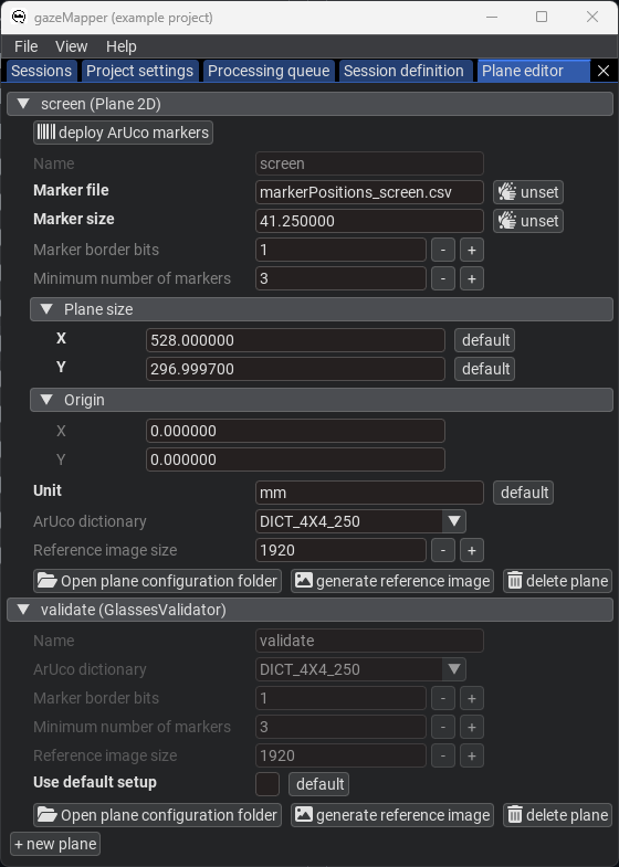
+ new planeagain and call itscreen. SelectPlane 2Das plane type. - Place the
markerPositions_screen.csvfile in the screen plane's setup folder (again use theOpen plane configuration folderbutton if needed). In the GUI, provide the name of this file for theMarker fileparameter. This file was also created using the calculations in the Excel sheet provided here. For more information about such plane definition files, see below. - Further configure the plane: set the
Marker sizeto41.25, theUnittomm, and the plane size toX:528andY:296.9997. See the below image for the final plane configuration.
- Click on
-
Back on the
Project settingspane, click onEpisode setup. Here we configure what episodes can be coded, and what plane(s) are associated with each episode.- For the
Episodes to code, add theValidation episode,Eye tracker synchronization episodeandTrial. - Under
Planes per episode, add all three above items. Set thevalidateplane for theValidation episodeandEye tracker synchronization episode, and thescreenplane for theTrialepisode. This indicates that for episode in the recording coded as validation or synchronization episodes only thevalidateplane will be searched for and processed, while for trials thescreenplane will be used.
- For the
-
Next, detection of the markers to delineate trials needs to be configured. On the
Project settingspane, click onEdit individual markersto configure these. -
Some settings also need to be configured on the
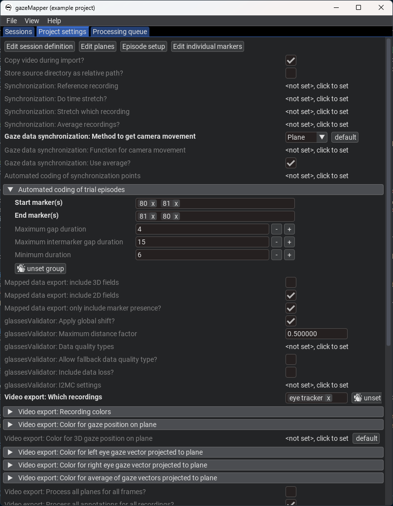
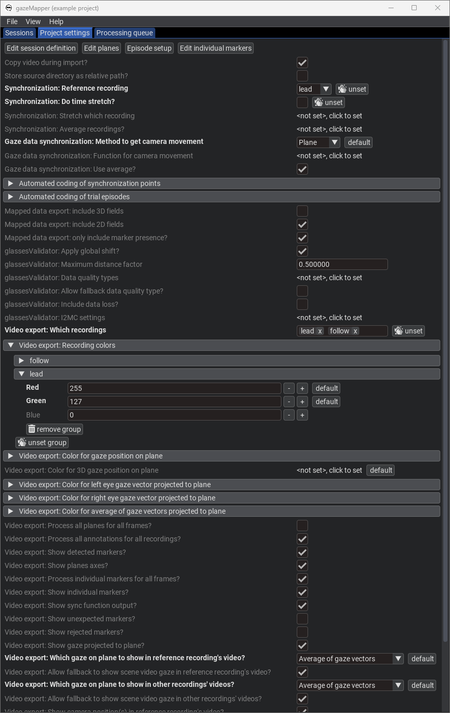
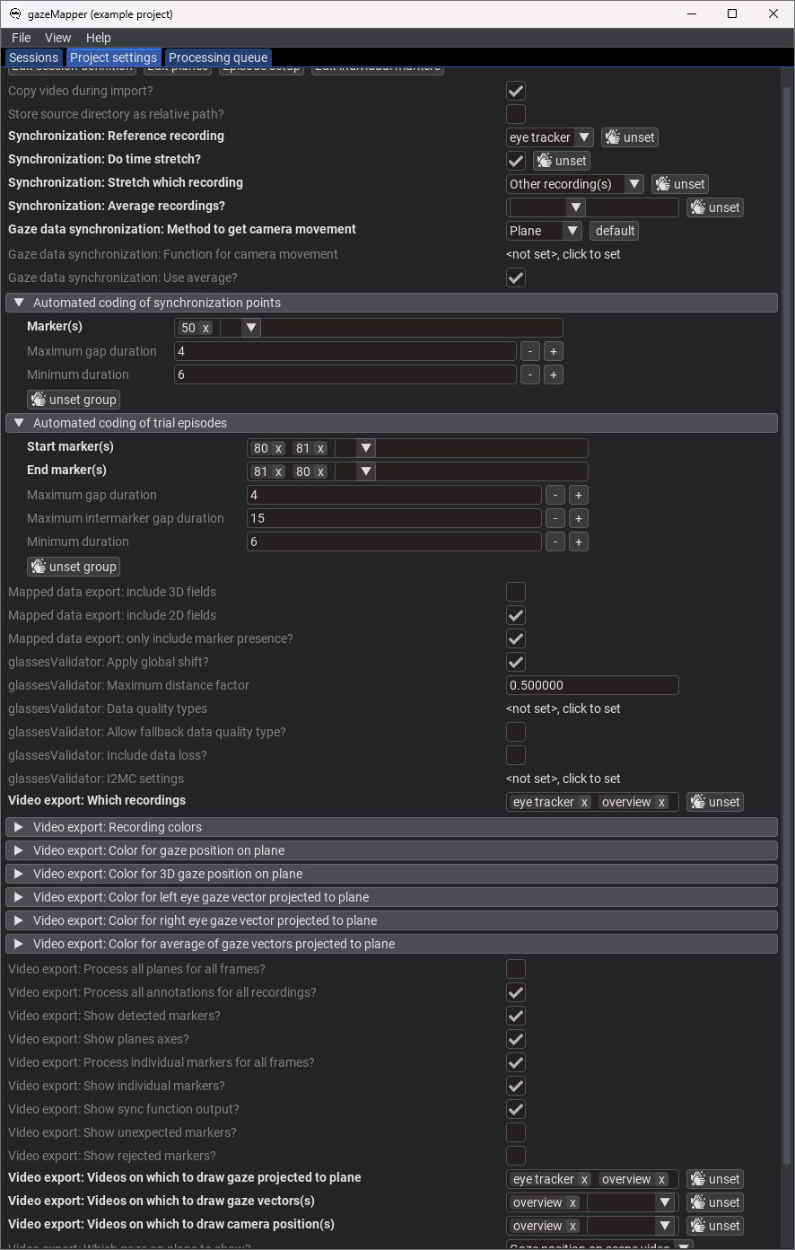
Project settingspage itself. Specifically, we need to set:Gaze data synchronization: Method to get camera movementtoPlaneas we'll use the glassesValidator plane for synchronizing gaze data and the scene camera.- Set up
Automated coding of trial episodesby clicking onclick to set. Expand the created settings. SetStart marker(s)to80 81andEnd marker(s)to81 80, since these are the markers used in the example in that order to denote trial starts and ends. For the rest of the settings the defaults are ok. Note that also different markers or marker sequences can be used for starts and ends. - When processing the recording, we want to output a scene video with detected markers and gaze projected to the validation and screen planes. To set this up, set
Video export: which recordingstoeye tracker, the name of the recording we defined in the session definition. - Furthermore, set up a color with which to draw gaze in the
Video export: recording colorsfield, using the colorRed:255,Green:127andBlue:0. - Set
Video export: Videos on which to draw gaze projected to planetoeye tracker. - Finally, open
Video export: Color for 3D gaze position on the planeand clickUnset groupto unset that color, which means that that gaze type will not be drawn on the video.
-
-
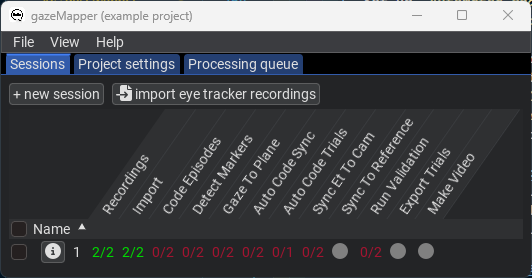
Now that the project is set up, we are ready to import and process recordings.
-
On the
Sessionpane, clickimport eye tracker recordings. There, select the folder containing the example data and indicate its anSMI ETGrecording. Note that you could also trigger import by drag-dropping a data folder onto gazeMapper. Note also that an SMI ETG recording has to be prepared before it can be imported by gazeMapper. This preparation has already been performed for the included example data. -
On the window that pops up, click
+ new session, and name the session1(or any name you like). Expand session1. You should now see the following: -
Assign the recording to the session by dragging it from the right, and dropping it on the left where it says
drop recording here. -
Click
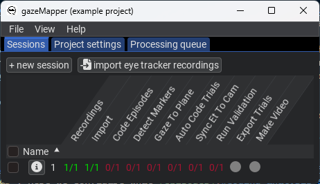
Continue. The recording will now be imported. When this is done, you should see the following: -
Next, run the
Detect markersaction by right-clicking on session1and selecting the action from the menu. This will detect all markers in the video, including those needed for automatic trial coding. -
When the
Detect markersaction is finished, run theAuto code trialsaction. -
Next, run the
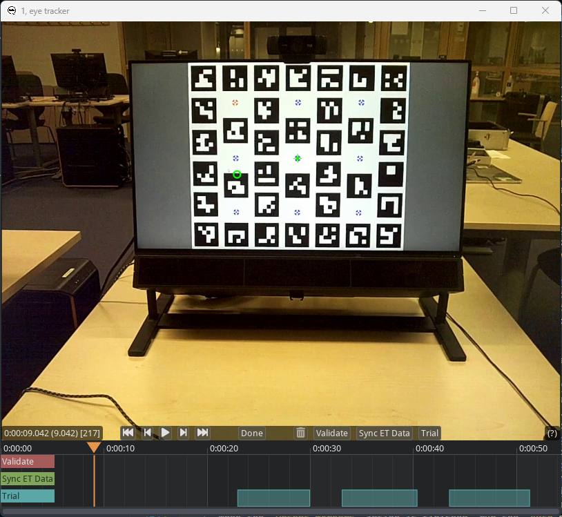
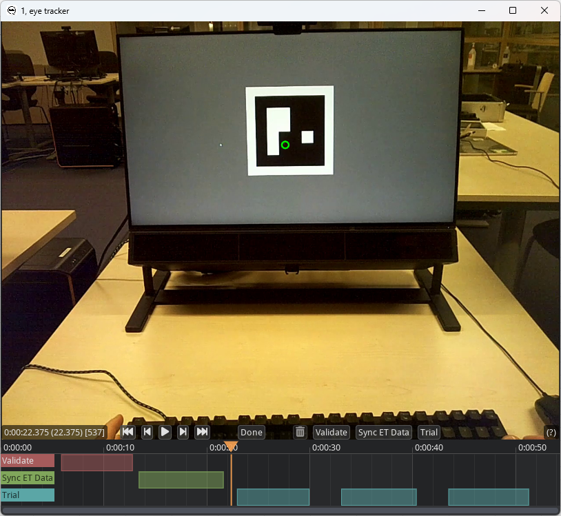
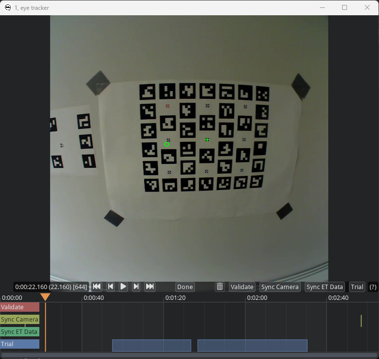
Code episodesaction. This will bring up a coding GUI used for annotating where the episodes of interest are in the recording.Trialshould already have been coded (see image below), use the GUI to check if trial starts and ends have been accurately determined. -
Use the seek functionality in the coder (you can press on the timeline underneath the video at the same height as the orange triangle, or use the video player controls) to find the start of the validation episode. Code the validation interval as described in step 5 in the glassesValidator manual. Furthermore, code the eye tracker synchronization episode as the beginning of the fixation on the center validation target before the participant starts nodding no and yes, and the end of the episode as the end of the fixation on the center validation target after the nodding:
Press
Doneto close the episode coding GUI. The coding file for this example can be found here. -
Next, run the
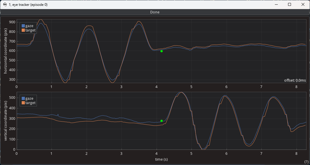
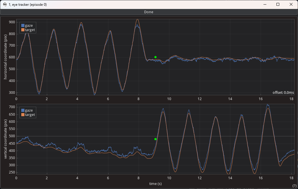
Sync et to camaction. This will open the following window:To align the two signals in time with each other, drag the green dot in the middle of either plot. The horizontal offset is the applied time shift (indicated by the value in the lower-right corner of the upper plot). Any vertical shift is not stored, but can be useful when aligning the two signals. When done aligning the two signals, press done atop the window.
-
Next, run the
Gaze to planeaction. -
Next, run the
Validationaction. -
Finally, run the
Make videoaction, which draws the detected markers, the participant's gaze and the projection of that gaze to the plane on the scene video, along with information about the episode annotations. -
Now, you can export the gaze data projected to the plane, the created video and the glassesValidator data quality measures to a folder of your choosing using the
Export trialsaction. An export for this example after following the above steps is available here.
-
Example 2 is an extension of example 1, scaling it up to recording two participants who are simultaneously recorded while viewing both their own and each others' screens on which three images are shown in sequence. At the start of the recording, like in example 1, both participants are furthermore asked to look at a glassesValidator poster (Niehorster et al., 2023), to make it possible to determine data quality measures for the recording. Finally, the glassesValidator poster is also used for synchronizing the eye tracker's gaze data with its scene camera. We strongly recommend collecting data for both synchronization and data quality determination for all wearable eye tracker recordings.
Example data, the configuration and the coding files needed for exactly recreating the below steps are provided. The stimulus presentation code is the same example 1, except that for one of the stimulus presentation computers sync_marker_qshow should be set to true, and for the other computer plane_which should be set to 2. Note that to keep the example simple, image presentation on the two systems was not synchronized other than by the two participants attempting to synchronize their key presses. Any real experiment would likely synchronize stimulus presentation on the two computers, e.g. using Lab Streaming Layer.
Steps 1 and 2 are mostly the same as for Example 1, with the following additional points to note:
- The two participants perform validation with glassesValidator poster, and nodding no and yes for eye tracker synchronization one after the other. This ensures that only one glassesValidator is shown at a time across the stimulus computers. Should both posters be presented at the same time, troubles may arise where part of one poster may be visible for the other eye tracker. This would severely interfere with the ability to determine where the glassesValidator plane is, cause the output of the validation routine to be wildly off. Should simultaneous validation be required, a second glassesValidator poster should be made using a set of markers that does not overlap with the markers used on the first poster. See the glassesValidator manual for instructions about customizing the poster. More generally, care should be taken to only use unique markers during a recording and not have any marker appear in more than one plane or as one of the trial delineation or synchronization markers.
- The stimulus presentation program now also shows synchronization markers at the start and end of the recording. These are used to provide visual transients in both scene camera streams that can be used to synchronize the two recordings together. Using ArUco markers, these transients can be automatically detected, but any transient visible to all cameras can be used and the moment at which it occurs manually coded.
Nonetheless, below we provide a full description of how recording preparation, data recording, and data analysis for this example were performed:
-
The researcher prepares the recording space. This involves
- Preparing a glassesValidator poster (see steps 1 and 2 here), either printed so it can be hung in a convenient location (best such that it is not in view of the eye-tracker's scene camera during the rest of the experiment), or shown on a projector or another computer screen. It is important that the exact size of the ArUco markers and their location is known.
- A plane to which the gaze data will be projected needs to be delineated using ArUco markers. While in this example we achieve that by presenting ArUco markers on a computer monitor together with the stimulus images, it could also be achieved by attaching ArUco markers to the edge of the screen. More generally, any planar surface can be used by placing a sufficient number of ArUco markers on it. While there are no hard requirements on the number of ArUco markers that need to be visible in a scene camera video frame for the mapping of gaze to the plane to succeed, it is recommended to aims for at the very minimum a handful of markers that cover a reasonable space to achieve a high probability that the plane is detected correctly. We recommend that users pilot test extensively, under the lighting conditions of the experiment and using participant behavior expected during the experiment (given that both lower light and faster participant movements may decrease the likelihood that markers are detected successfully).
It is important that the exact positions, sizes and orientations of the individual ArUco markers are known. This is required for gazeMapper to be able to correctly determine the observer's position and orientation with respect to the plane, allowing for gaze to be projected to the plane. This information has to be provided to gazeMapper. For more information, see gazeMapper planes.
-
A recording then proceeds as follows.
- Both participants are positioned in front of the stimulus screens. One participant is designated the
lead, the other thefollower(they could for instance be teacher and student, and also the names used could of course be anything). - Both participants look at the screen of the lead participant, where an ArUco marker is shown for automatic synchronization.
- One participant is first presented with the glassesValidator poster and completes a glassesValidator data collection (see step 3 here). Note that in the example, the validation is not performed at arm's length, but at the distance at which the rest of the task will be completed. If a single distance is predominant during an experiment, using a specific distance for the validation data collection is recommended.
- After this, while the participant remains at the same position, they are instructed to continuously fixate the fixation target at the center of the validation poster while slowly nodding no with their head five times, and then slowly nodding yes five times.
- When the first participant is done, the other participant performs the same validation and synchronization procedure from the last two steps.
- The main task commences. In the example, the participants simply view pictures presented on their screen and also look at each other's screens. They press the spacebar when they are done viewing the picture, after which a new picture is shown. Rough synchronization between the presentations is maintained by the participants attempting to press the spacebar in synchrony. On both screens, each picture presentation is preceded and succeeded by a sequence of single ArUco markers that allows to automatically delineate the trials in the recording. Note however that the trial delineation of the lead recording will be used by both recordings in gazeMapper.
- Finally, both participants look at the screen of the lead participant again, where another ArUco marker is shown for synchronization.
- Both participants are positioned in front of the stimulus screens. One participant is designated the
-
To start processing a recording with gazeMapper, a gazeMapper project first needs to be created and configured. If you want to skip the configuration and just quickly test out gazeMapper, you can create a new gazeMapper project following the first step below, and then simply replace the content of this project's config folder with the configuration provided here. Reopen the project in gazeMapper after replacing the configuration and skip to step 4.
-
Run gazeMapper and make a new gazeMapper project.
-
You will be greeted by the following screen, go to the
Project settingspane. -
First we have to tell gazeMapper what recordings to expect for a session, click on
Edit session definitionto do so. -
Click
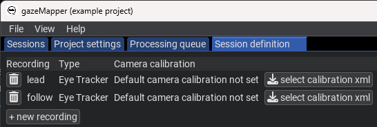
+ new recordingto define two recordings. We'll call oneleadand the otherfollow. SelectEye Trackeras recording type for both. The screen will now look as follows. -
Back on the
Project settingspane, click onEdit planes. Here we need to add both the glassesValidator poster and the stimulus screen as planes.- Click on
+ new planeand call itvalidate. SelectGlassesValidatoras plane type. - Since the example did not use the default glassesValidator poster printed on A2 format but instead presented the glassesValidator poster on screen, a custom glassesValidator setup is needed. To set this up, uncheck the
Use default setupbutton for the validate plane. Press theOpen plane configuration folderbutton to open the plane's configuration folder. The files there will have to be edited outside of gazeMapper to reflect the glassesValidator poster as presented on the computer screen. For this example, use the files available here, which were created based on calculations in the Excel sheet provided here. Besides custommarkerPositions.csvandtargetPositions.csvfiles to correctly specify the location of validation targets and ArUco markers on the screen, also thevalidationSetup.txtfile was edited to set the correct size for the ArUco markers (markerSidevariable), the validation targets' diameter (targetDiameter) and the size of the plane (gridColsandgridRows, which were set to the size of the monitor). Note that for glassesValidator, these sizes and positions are specified in cm, not mm. - Add two more planes using the
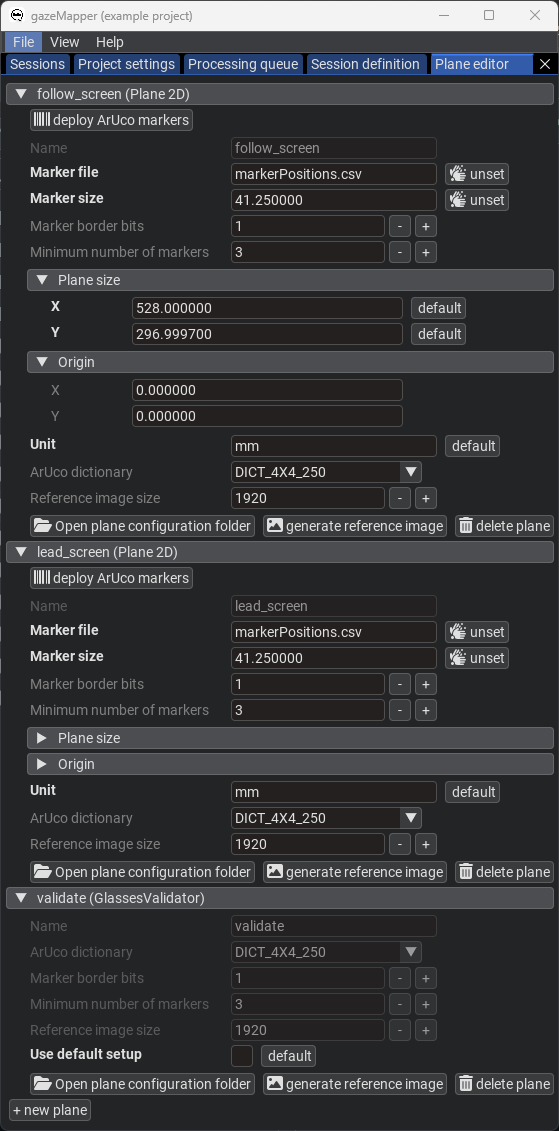
+ new planebutton. Call themlead_screenandfollow_screen. SelectPlane 2Das plane type for both. - Place the
markerPositions_screen.csvfiles found here for the screens in the respective screen plane's setup folder (again use theOpen plane configuration folderbutton if needed). In the GUI, provide the names of these files for theMarker fileparameter. These files were also created using the calculations in the Excel sheet provided here. For more information about such plane definition files, see below. - Further configure both planes: set the
Marker sizeto41.25, theUnittomm, and the plane size toX:528andY:296.9997. See the below image for the final plane configuration.
- Click on
-
Back on the
Project settingspane, click onEpisode setup. Here we configure what episodes can be coded, and what plane(s) are associated with each episode.- For the
Episodes to code, add theValidation episode,Camera sync point,Eye tracker synchronization episodeandTrial. - Under
Planes per episode, add theValidation episode,Eye tracker synchronization episodeandTrialitems. Set thevalidateplane for theValidation episodeandEye tracker synchronization episode, and the twoscreenplanes for theTrialepisode. This indicates that for episode in the recording coded as validation or synchronization episodes only thevalidateplane will be searched for and processed, while for trials thescreenplanes will be used.
- For the
-
Next, detection of the markers to delineate trials needs to be configured. On the
Project settingspane, click onEdit individual markersto configure these. -
Some settings also need to be configured on the
Project settingspage itself. Specifically, we need to set:Synchronization: Reference recordingtolead.Synchronization: Do time stretch?to False (unchecked/disabled).Gaze data synchronization: Method to get camera movementtoPlaneas we'll use the glassesValidator plane for synchronizing gaze data and the scene camera.- Set up
Automated coding of synchronization episodesby clicking onclick to set. Expand the created settings. SetMarker(s)to50. For the rest of the settings the defaults are ok. Note also that multiple markers could be used as synchronization points. - Set up
Automated coding of trial episodesby clicking onclick to set. Expand the created settings. SetStart marker(s)to80 81andEnd marker(s)to81 80, since these are the markers used in the example in that order to denote trial starts and ends. For the rest of the settings the defaults are ok. Note that also different markers or marker sequences can be used for starts and ends. - When processing the recording, we want to output scene videos for both with detected markers and gaze of both participants projected to the validation and screen planes. To set this up, set both
leadandfollow(the names of the recordings we defined in the session definition) forVideo export: which recordings. - Furthermore, set up the colors with which to draw gaze in the
Video export: recording colorsfield. PressAdd itemand add both theleadandfollowrecordings. Forlead, use the colorRed:255,Green:127andBlue:0. Forfollow, use the colorRed:0,Green:95andBlue:191. - Open
Video export: Color for 3D gaze position on the planeand clickUnset groupto unset that color, which means that that gaze type will not be drawn on the video. - Set
Video export: Videos on which to draw gaze projected to plane,Video export: Videos on which to draw gaze vectors(s)andVideo export: Videos on which to draw camera position(s)all to bothfollowandlead. - For
Video export: Which gaze on plane to show?selectAverage of gaze vectors. This will use, if the eye tracker provides it, the intersection of the gaze vectors with the plane instead of the gaze position on the scene video. This may be more accurate, depending on the assumptions in the eye tracker for determining the scene position on the gaze video. Users are recommended to pilot what setting is most suitable for their project and equipment.
-
-
Now that the project is set up, we are ready to import and process recordings.
-
On the
Sessionpane, clickimport eye tracker recordings. There, select the folder containing the example data and indicate you're looking forTobii Glasses 2recordings. Note that you could also trigger import by drag-dropping a data folder onto gazeMapper. -
On the window that pops up, click
+ new session, and name the session1(or any name you like). Expand session1. You should now see the following: -
Assign the recording to the session by dragging it from the right, and dropping it on the left for the
leadrecording where it saysdrop recording here. ClickContinue. The recording will now be imported. -
Again click
import eye tracker recordings, select the folder containing the example data and this time indicate you're looking forPupil Invisiblerecordings. Assign the found Pupil Invisible recording to thefollowrecording.Note that in real use cases with more recordings that you can assign multiple recordings to one or multiple sessions in one go using this dialogue.
-
Click
Continue. The second recording will now be imported. When this is done, you should see the following: -
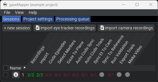
Next, run the
Detect markersaction by right-clicking on session1and selecting the action from the menu. This will detect all markers in the video, including those needed for automatic trial coding. -
When the
Detect markersaction is finished, run theAuto code syncandAuto code trialsactions. -
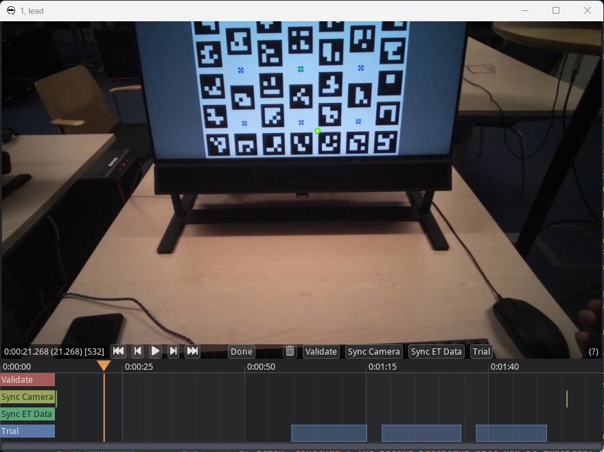
Next, run the
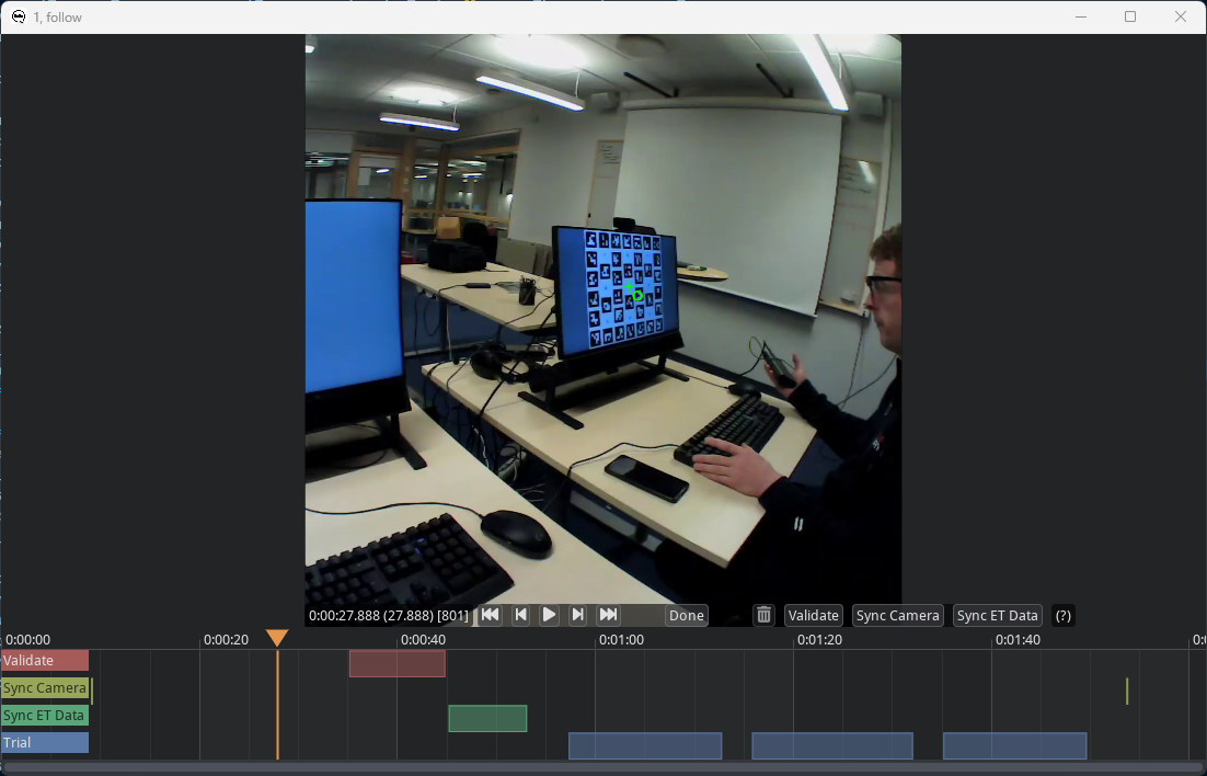
Code episodesaction. This will bring up a coding GUI used for annotating where the episodes of interest are in the recording.TrialandSync camerashould already have been coded (see image below), use the GUI to check if trial starts and ends and the synchronization timepoints have been accurately determined. -
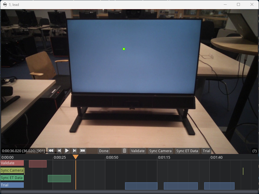
Use the seek functionality in the coder (you can press on the timeline underneath the video at the same height as the orange triangle, or use the video player controls) to find the start of the validation episode. Code the validation interval as described in step 5 in the glassesValidator manual. Furthermore, code the eye tracker synchronization episode as the beginning of the fixation on the center validation target before the participant starts nodding no and yes, and the end of the episode as the end of the fixation on the center validation target after the nodding:
Press
Doneto close the episode coding GUI. -
The coding GUI for the other recording of the session will now appear. Also code the validation and eye tracker synchronization episode for this recording. Once done it should look as follows:
Press
Doneto close the episode coding GUI. The coding files for this example can be found here. -
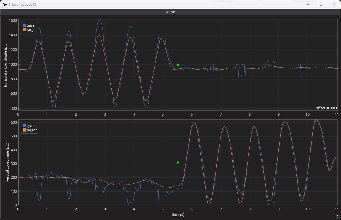
Next, run the
Sync et to camaction. This will open the following window:To align the two signals in time with each other, drag the green dot in the middle of either plot. The horizontal offset is the applied time shift (indicated by the value in the lower-right corner of the upper plot). Any vertical shift is not stored, but can be useful when aligning the two signals. When done aligning the two signals, press done atop the window.
-
Next, run the
Sync to referenceaction to synchronize the two recordings together. -
Next, run the
Gaze to planeaction. -
Next, run the
Validationaction. -
Finally, run the
Make videoaction, which draws the detected markers, the participant's gaze and the projection of that gaze to the plane on the scene video, along with information about the episode annotations. -
Now, you can export the gaze data projected to the plane, the created video and the glassesValidator data quality measures to a folder of your choosing using the
Export trialsaction. An export for this example after following the above steps is available here.
-
Example data, the configuration and the coding files needed for exactly recreating the below steps are provided. The stimulus material and used planes are also available.
Example 3 is a more advanced example, showing a recording of a participant looking at and interacting with multiple planes while also being filmed with an external overview camera. The participant is performing a super simplified stock counting task, where they count how many apples, pear and mangos are on images on an iPad and then report their counts on papers spread across the scene. At the start of the recording, the participant is furthermore asked to look at a glassesValidator poster (Niehorster et al., 2023), to make it possible to determine data quality measures for the recording. Finally, the glassesValidator poster is also used at both the start and the end of the recording for synchronizing the eye tracker's gaze data with its scene camera. The preparation, data recording, and data analysis for this example were performed as follows:
-
The researcher prepares the recording space. This involves
- Printing a glassesValidator poster (see steps 1 and 2 here) and hanging it on the wall.
- Preparing the stimulus material on the iPad, including ArUco markers to define the stimulus plane, and ArUco markers for automatic delineation of trials and automatic synchronization of the eye tracker and the overview camera.
- Multiple further planes for the fruit counts have to be printed and distributed around the recording space.
- Set up an external camera. Set it up such that both the observer and the various planes are in view during the whole recording, such that a sufficient number of markers is visible in each recording, and use that reflections of the environment on the tablet do not cause issues with later processing of the recording. Note here that during pilot recordings of this example, we ran into issues with ArUco markers being reflected in the tablet and being detected by gazeMapper, and with the lighting in the room making part of the tablet screen illegible. To solve this, we have adjusted camera positions and selectively switched off lights to alleviate these issues.
As in the previous examples, it is important that the exact positions, sizes and orientations of the individual ArUco markers are known. This is required for gazeMapper to be able to correctly determine the observer's position and orientation with respect to each plane, allowing for gaze to be projected to these planes. This information has to be provided to gazeMapper. For more information, see gazeMapper planes.
-
A recording then proceeds as follows.
- First the participant holds up the iPad so that the overview camera can see the contents of its screen, and also looks at the iPad. They then activate the PowerPoint presentation on the iPad, which flashes a synchronization marker on the screen, which will be used in analysis to synchronize the overview camera to the eye tracker recording.
- Then, the participant is positioned in front of the glassesValidator poster and completes a glassesValidator data collection (see step 3 here).
- After this, while the participant remains at the same position, they are instructed to continuously fixate the fixation target at the center of the validation poster while slowly nodding no with their head five times, and then slowly nodding yes five times.
- Next, the main task commences. The participant again picks up the iPad and continues the PowerPoint presentation. Next in the presentation two ArUco markers are shown in sequence that allows to automatically delineate the trials in the recording. Then, a stimulus image is shown. The participant counts the number of apples, pear and mangos in the image, and writes their count on the paper for the respective fruit. Once done, they continue the presentation. A sequence of ArUco markers is shown signalling the end of the trial, and thereafter another sequence signalling the start of the next trial. The participant again writes down their fruit count and advances the presentation, upon which the trial end ArUco marker sequence is again shown.
- They then stand in front of the glassesValidator poster and again slowly nod no with their head five times, and then slowly nod yes five times while maintaining fixation of the fixation target at the center of the validation poster.
- Finally, the participant holds up the iPad to the overview camera and advances the presentation, upon which another ArUco marker for synchronization is shown.
-
To start processing a recording with gazeMapper, a gazeMapper project first needs to be created and configured. If you want to skip the configuration and just quickly test out gazeMapper, you can create a new gazeMapper project following the first step below, and then simply replace the content of this project's config folder with the configuration provided here. Reopen the project in gazeMapper after replacing the configuration and skip to step 4.
-
Run gazeMapper and make a new gazeMapper project.
-
You will be greeted by the following screen, go to the
Project settingspane. -
First we have to tell gazeMapper what recordings to expect for a session, click on
Edit session definitionto do so. -
Click
+ new recordingto define two recordings. We'll call oneeye trackerand the otheroverview. SelectEye Trackeras recording type for the eye tracker recording, and Camera as the type for the overview recording. Next, add a camera calibration file for the camera recording (this is not needed for the eye tracker recordings, as the used eye tracker provides a calibration for the scene camera). To do so, click theselect calibration xmlbutton, and load this file. The screen will now look as follows. -
Back on the
Project settingspane, click onEdit planes. Here we need to add the glassesValidator poster, the iPad screen and the three answer sheets as planes.- Click on
+ new planeand call itvalidate. SelectGlassesValidatoras plane type. Since the default A2 glassesValidator poster was used, this plane requires no further configuration. - Add four more planes using the
+ new planebutton. Call themtabletandapples,pearsandmangos. SelectPlane 2Das plane type for all four. - Place the
markerPositions.csvfiles found here for the four planes in the respective plane's setup folders (use theOpen plane configuration folderbutton in gazeMapper to find the plane's folder, if needed). In the GUI, provide the names of these files for theMarker fileparameter. These files were created using the calculations in the Excel sheet provided here. For more information about such plane definition files, see below. - Further configure the planes: for the tablet plane, set the
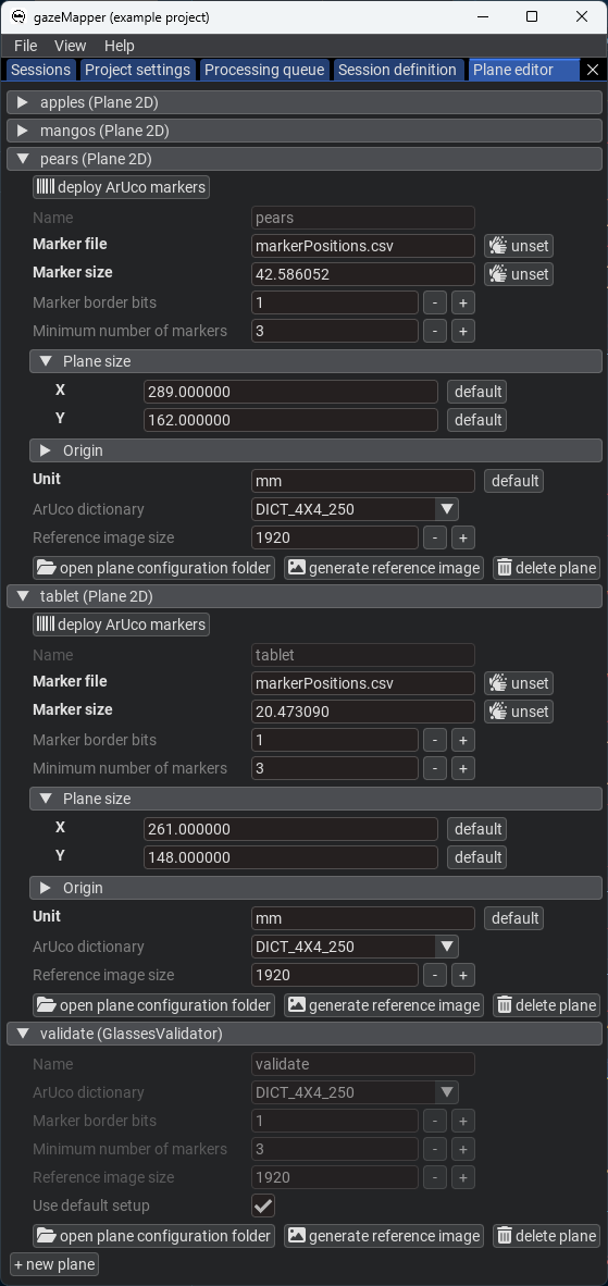
Marker sizeto20.47309, set it to42.586052for the other three planes. For the tablet plane, set the plane size toX:261andY:148, for the other three planes set it toX:189andY:162. For all four planes, set theUnittomm. See the below image for part of the final plane configuration.
- Click on
-
Back on the
Project settingspane, click onEpisode setup. Here we configure what episodes can be coded, and what plane(s) are associated with each episode.- For the
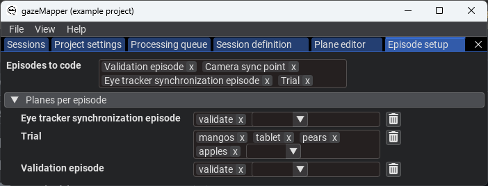
Episodes to code, add theValidation episode,Camera sync point,Eye tracker synchronization episodeandTrial. - Under
Planes per episode, add theValidation episode,Eye tracker synchronization episodeandTrialitems. Set thevalidateplane for theValidation episodeandEye tracker synchronization episode, and the four other planes for theTrialepisode. This indicates that for episodes in the recording coded as validation or synchronization episodes only thevalidateplane will be searched for and processed, while for trials the other four planes will be used.
- For the
-
Next, detection of the markers to delineate trials needs to be configured. On the
Project settingspane, click onEdit individual markersto configure these. -
Some settings also need to be configured on the
Project settingspage itself. Specifically, we need to set:Synchronization: Reference recordingtoeye tracker.Synchronization: Do time stretch?to True (checked/enabled).Synchronization: Stretch which recording?toOther recording(s).- Click
Synchronization: Average recordings?to create the setting, but do not assign any recording, since we do not want to use this functionality. Gaze data synchronization: Method to get camera movementtoPlaneas we'll use the glassesValidator plane for synchronizing gaze data and the scene camera.- Set up
Automated coding of synchronization episodesby clicking onclick to set. Expand the created settings. SetMarker(s)to50. For the rest of the settings the defaults are ok. Note also that multiple markers could be used as synchronization points. - Set up
Automated coding of trial episodesby clicking onclick to set. Expand the created settings. SetStart marker(s)to80 81andEnd marker(s)to81 80, since these are the markers used in the example in that order to denote trial starts and ends. For the rest of the settings the defaults are ok. Note that also different markers or marker sequences can be used for starts and ends. - When processing the recording, we want to output scene videos for both with detected markers and gaze of both participants projected to the validation and screen planes. To set this up, set both
eye trackerandoverview(the names of the recordings we defined in the session definition) forVideo export: which recordings. - Furthermore, set up the colors with which to draw gaze in the
Video export: recording colorsfield. PressAdd itemand add theeye trackerrecording (the overview recording cannot be added as it has no gaze data). For theeye trackerrecording, use the colorRed:255,Green:127andBlue:0. - Finally set
Video export: Videos on which to draw gaze projected to plane,Video export: Videos on which to draw gaze vectors(s)andVideo export: Videos on which to draw camera position(s)all tooverview. ForVideo export: Videos on which to draw gaze projected to plane, also specifyeye tracker. SetVideo export: Gaze position marginto0.1.
-
-
Now that the project is set up, we are ready to import and process recordings.
-
On the
Sessionpane, clickimport eye tracker recordings. There, select the folder containing the example data and indicate you're looking forPupil Invisiblerecordings. Note that you could also trigger import by drag-dropping a data folder onto gazeMapper. -
On the window that pops up, click
+ new session, and name the session1(or any name you like). Expand session1. You should now see the following: -
Assign the recording to the session by dragging it from the right, and dropping it on the left for the
eye trackerrecording where it saysdrop recording here. ClickContinue. The recording will now be imported. -
Click
import camera recordings, select the folder containing the example data and click continue. Assign the found camera recording (cam1_R003_reencode.mp4) to theoverviewrecording.Note that in real use cases with more recordings that you can assign multiple recordings to one or multiple sessions in one go using these dialogues.
-
Click
Continue. The camera recording will now be imported. When this is done, you should see the following: -
Next, run the
Detect markersaction by right-clicking on session1and selecting the action from the menu. This will detect all markers in the video, including those needed for automatic trial coding. -
When the
Detect markersaction is finished, run theAuto code syncandAuto code trialsactions. -
Next, run the
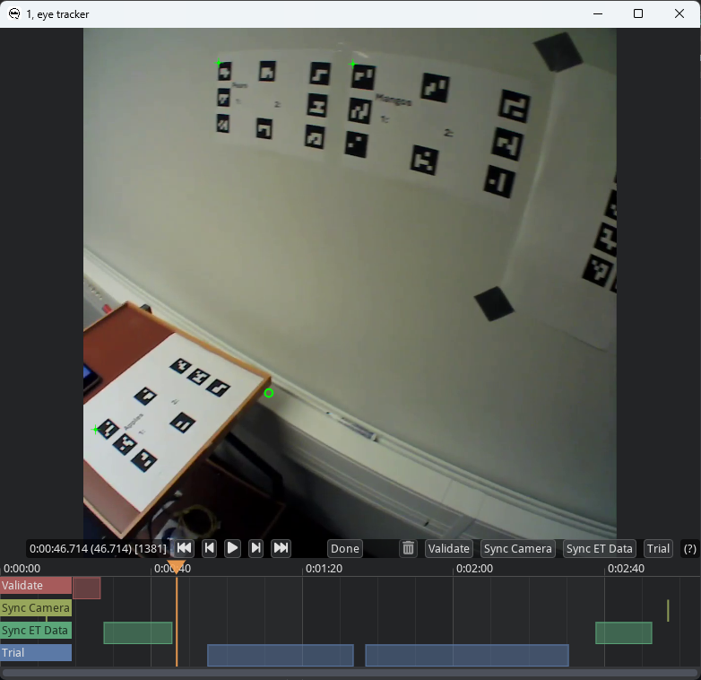
Code episodesaction. This will bring up a coding GUI used for annotating where the episodes of interest are in the recording.TrialandSync camerashould already have been coded (see image below), use the GUI to check if trial starts and ends and the synchronization timepoints have been accurately determined. -
Use the seek functionality in the coder (you can press on the timeline underneath the video at the same height as the orange triangle, or use the video player controls) to find the start of the validation episode. Code the validation interval as described in step 5 in the glassesValidator manual. Furthermore, code the eye tracker synchronization episode as the beginning of the fixation on the center validation target before the participant starts nodding no and yes, and the end of the episode as the end of the fixation on the center validation target after the nodding. Code both the episode at the beginning of the recording and the episode near the end of the recording:
Press
Doneto close the episode coding GUI. -
The coding GUI for the other recording of the session will now appear. Here too, check that the synchronization timespoints are correctly coded. Press
Doneto close the episode coding GUI. The coding files for this example can be found here. -
Next, run the
Sync et to camaction. This will open the following window:To align the two signals in time with each other, drag the green dot in the middle of either plot. The horizontal offset is the applied time shift (indicated by the value in the lower-right corner of the upper plot). Any vertical shift is not stored, but can be useful when aligning the two signals. When done aligning the two signals, press done atop the window.
-
Next, run the
Sync to referenceaction to synchronize the two recordings together. -
Next, run the
Gaze to planeaction. -
Next, run the
Validationaction. -
Finally, run the
Make videoaction, which draws the detected markers, the participant's gaze and the projection of that gaze to the plane on the scene video, along with information about the episode annotations. -
Now, you can export the gaze data projected to the plane, the created video and the glassesValidator data quality measures to a folder of your choosing using the
Export trialsaction. An export for this example after following the above steps is available here.
-
The gazeMapper GUI organizes recordings into a project folder. Each session to be processed is represented by a folder in this project folder, and one or multiple recordings are stored in subfolders of a session folder. After importing recordings, all further processing is done inside these session and recording folders. The source directories containing the original recordings remain
untouched when running gazeMapper. A gazeMapper project folder furthermore contains a folder config specifying the configuration
of the project. So an example directory structure may look like:
my project/
├── config/
│   ├── plane 1/
│   ├── plane 2/
│   └── validation plane/
├── session 01/
│   ├── teacher/
│   ├── student/
│   └── overview camera/
├── session 02/
│   ├── teacher/
│   ├── student/
│   └── overview camera/
...
where session 01 and session 02 are individual recording session, each made up of a teacher, a student and an overview camera recording. plane 1 and plane 2 contain definitions of planes that gazeMapper will map gaze to and validation plane is an additional plane used for validation of the eye tracker's calibration using glassesValidator, see below for documentation.
When not using the GUI and running gazeMapper using your own scripts, such a project folder organization is not required. Working folders
for a session can be placed anywhere (though recording folders should be placed inside a session folder), and a folder for a custom configuration can also be placed anywhere (but its location needs to be provided using the config_dir argument of all the functions in gazeMapper.process). The gazeMapper.process functions simply take the path to a session or recording folder.
During the importing and processing of a session, or an eye tracker or camera recording, a series of files are created in the working folder of the session and the recording(s). These are the following (not all of the files are created for a camera recording, for instance, there is no gaze data associated with such a recording):
| file | location | produced by |
description |
|---|---|---|---|
calibration.xml |
recording | Session.import_recording |
Camera calibration parameters for the (scene) camera. |
frameTimestamps.tsv |
recording | Session.import_recording |
Timestamps for each frame in the (scene) camera video. |
gazeData.tsv |
recording | Session.import_recording |
Gaze data cast into the glassesTools common format used by gazeMapper. Only for eye tracker recordings. |
recording_info.json |
recording | Session.import_recording |
Information about the recording. |
recording.gazeMapper |
recording | Session.import_recording |
JSON file encoding the state of each recording-level gazeMapper action. |
worldCamera.mp4 |
recording | Session.import_recording |
Copy of the (scene) camera video (optional, depends on the import_do_copy_video option). |
coding.tsv |
recording | process.code_episodes |
File denoting the analysis, synchronization and validation episodes to be processed. This is produced with the coding interface included with gazeMapper. Can be manually created or edited to override the coded episodes. |
planePose_<plane name>.tsv |
recording | process.detect_markers |
File with information about plane pose w.r.t. the (scene) camera for each frame where the plane was detected. |
markerPose_<marker ID>.tsv |
recording | process.detect_markers |
File with information about marker pose w.r.t. the (scene) camera for each frame where the marker was detected. |
planeGaze_<plane name>.tsv |
recording | process.gaze_to_plane |
File with gaze data projected to the plane/surface. Only for eye tracker recordings. |
validate_<plane name>_* |
recording | process.run_validation |
Series of files with output of the glassesValidator validation procedure. See the glassesValidator readme for descriptions. Only for eye tracker recordings. |
VOR_sync.tsv |
recording | process.sync_et_to_cam |
File containing the synchronization offset (s) between eye tracker data and the scene camera. Only for eye tracker recordings. |
detectOutput.mp4 |
recording | process.make_video |
Video of the eye tracker scene camera or external camera (synchronized to one of the recordings if there are multiple) showing detected plane origins, detected individual markers and gaze from any other recordings eye tracker recordings. Also shown for eye tracker recordings are gaze on the scene video from the eye tracker, gaze projected to the detected planes. Each only if available, and enabled in the video generation settings. |
session.gazeMapper |
session | Session.import_recording |
JSON file encoding the state of each session-level gazeMapper action. |
ref_sync.tsv |
session | process.sync_to_ref |
File containing the synchronization offset (s) and other information about sync between multiple recordings. |
planeGaze_<recording name>.tsv |
session | process.export_trials |
File containing the gaze position on one or multiple planes. One file is created per eye tracker recording. |
gazeMapper produces data in the reference frame of a plane/surface. This 2D data is stored in the planeGaze_* files produced when exporting the gazeMapper results, and also in the planeGaze_* files stored inside individual recordings' working folders.
The gaze data in these files has its origin (0,0) at a position that is specified in the plane setup (or in the case of a glassesValidator poster at the center of the fixation target that was indicated to be the center target with the centerTarget setting in the validation poster's validationSetup.txt configuration file). The positive x-axis points to the right and the positive y-axis
downward, which means that (-,-) coordinates are to the left and above of the plane origin, and (+,+) to the right and below.
gazeMapper supports the following eye trackers:
- AdHawk MindLink
- Pupil Core
- Pupil Invisible
- Pupil Neon
- SeeTrue STONE
- SMI ETG 1 and ETG 2
- Tobii Pro Glasses 2
- Tobii Pro Glasses 3
Pull requests or partial help implementing support for further wearable eye trackers are gladly received. To support a new eye tracker, implement it in glassesTools.
For some eye trackers, the recording delivered by the eye tracker's recording unit or software can be directly imported into gazeMapper. Recordings from some other eye trackers however require some steps to be performed in the manufacturer's software before they can be imported into gazeMapper. These are:
- Pupil Labs eye trackers: Recordings should either be preprocessed using Pupil Player (Pupil Core and Pupil Invisible),
Neon Player (Pupil Neon) or exported from Pupil Cloud (Pupil Invisible and Pupil Neon).
- Using Pupil Player (Pupil Core and Pupil Invisible) or Neon player (Pupil Neon): Each recording should 1) be opened
in Pupil/Neon Player, and 2) an export of the recording (
ehotkey) should be run from Pupil/Neon Player. Make sure to disable theWorld Video Exporterin thePlugin Managerbefore exporting, as the exported video is not used by glassesTools and takes a long time to create. If you want pupil diameters, make sure to enableExport Pupil Positionsin theRaw Data Exporter, if available. Note that importing a Pupil/Neon Player export of a Pupil Invisible/Neon recording may require an internet connection. This is used to retrieve the scene camera calibration from Pupil Lab's servers in case the recording does not have acalibration.binfile. - Using Pupil Cloud (Pupil Invisible and Pupil Neon): Export the recordings using the
Timeseries data + Scene videoaction. - For the Pupil Core, for best results you may wish to do a scene camera calibration yourself, see https://docs.pupil-labs.com/core/software/pupil-capture/#camera-intrinsics-estimation. If you do not do so, a generic calibration will be used by Pupil Capture during data recording, by Pupil Player during data analysis and by the glassesTools processing functions, which may result in incorrect accuracy values.
- Using Pupil Player (Pupil Core and Pupil Invisible) or Neon player (Pupil Neon): Each recording should 1) be opened
in Pupil/Neon Player, and 2) an export of the recording (
- SMI ETG: For SMI ETG recordings, access to BeGaze is required and the following steps should be performed:
- NB: Note that it is critical that a
SYNC_ET_TO_CAMaction is performed for SMI ETG recordings. This is required because the gaze timestamps in the export file created below have an unknown zero that is not related to the scene video clock, and no info about offset between these clocks is available. The gaze signal and video feed have to be manually aligned (synchronized). - Export gaze data:
Export->Legacy: Export Raw Data to File.- In the
Generaltab, make sure you select the following:Channel: enable both eyesPoints of Regard (POR): enableGaze position,Eye position,Gaze vectorBinocular: enableGaze positionMisc Data: enableFrame counter- disable everything else
- In the Details tab, set:
Decimal placesto 4Decimal separatortopointSeparatortoTab- enable
Single file output
- This will create a text file with a name like
<experiment name>_<participant name>_<number> Samples.txt(e.g.005-[5b82a133-6901-4e46-90bc-2a5e6f6c6ea9]_005_001 Samples.txt). Move this file/these files to the recordings folder and rename them. If, for instance, the folder contains the files005-2-recording.avi,005-2-recording.idfand005-2-recording.wav, amongst others, for the recording you want to process, rename the exported samples text file to005-2-recording.txt.
- In the
- Export the scene video:
- On the Dashboard, double click the scene video of the recording you want to export to open it in the scanpath tool.
- Right click on the video and select settings. Make the following settings in the
Cursortab:- set
Gaze cursortotranslucent dot - set
Line widthto 1 - set
Sizeto 1
- set
- Then export the video,
Export->Export Scan Path Video. In the options dialogue, make the following settings:- set
Video Sizeto the maximum (e.g.(1280,960)in my case) - set
Frames per secondto the framerate of the scene camera (24 in my case) - set
EncodertoPerformance [FFmpeg] - set
QualitytoHigh - set
Playback speedto100% - disable
Apply watermark - enable
Export stimulus audio - finally, click
Save as, navigate to the folder containing the recording, and name it in the same format as the gaze data export file we created above but replacingrecordingwithexport, e.g.005-2-export.avi.
- set
- NB: Note that it is critical that a
A gazeMapper session represents a single recording session. It may consist of only a single eye tracker recording, but could also contain multiple (simultaneous) eye tracker and external camera recordings. When setting up a gazeMapper project, one first defines what recordings to expect for a recording session. This is done in the Session definition pane in the GUI or by means of a gazeMapper.session.SessionDefinition object. A session definition contains a list of expected recordings, which are defined using the + new recording button on the Session definition pane in the GUI, or by means of gazeMapper.session.RecordingDefinition objects passed to gazeMapper.session.SessionDefinition.add_recording_def(). Each recording definition has a name and an eye tracker type (gazeMapper.session.RecordingType), where the type can be an eye tracker recording (gazeMapper.session.RecordingType.Eye_Tracker) or a (external) camera recording (gazeMapper.session.RecordingType.Camera). This session definition is typically stored in a JSON file session_def.json in the configuration directory of a gazeMapper project.
As outlined above, each gazeMapper session is its own folder inside a gazeMapper project. The name of the session is simply the name of the folder (which we will term the session working folder). You can thus rename a session by renaming its working folder. Similarly, each recording's working folder is stored inside the session working folder, with as folder name the name defined for the corresponding recording in the session definition. You are advised not to manually rename these folders, as folders with a name different than that defined in the session definition are not recognized by gazeMapper.
When opening a gazeMapper project folder, each subfolder of the project folder containing a session.gazeMapper status file is taken to be a session, regardless of whether it has recording working folders or not. Similarly, recording working folders in a session working folder with names that match the recordings defined in the project's session definition will be loaded automatically.
The main goal of gazeMapper is to map head-referenced gaze data recording with a wearable eye tracker to one or multiple planes in the world. That means that gazeMapper determines where on the plane a participant looks, regardless of where in their visual field the plane appears, and that gazeMapper's output expresses gaze in the plane's reference frame. To be able to perform this mapping, gazeMapper needs to be able to determine where the participant is located in space and how they are oriented with respect to the plane (that is, their pose). This is done by placing an array of fiducial markers of known size and known spatial layout on the plane that can be detected through computer vision and used to determine the participant's pose. See the example above for what such an array of fiducial markers looks like.
For gazeMapper to be able to do its job, it needs to have precise information about the array of fiducial markers that defines the plane(s). When designing these arrays, it is important to use unique markers (in other words, each marker may only be used once across all planes and other markers that appear in the recording, e.g. for synchronization or automatic trial coding). Any dictionary of fiducial markers understood by OpenCV's ArUco module (cv2.aruco, see cv::aruco::PREDEFINED_DICTIONARY_NAME) is supported (i.e. various ArUco marker dictionaries, as well as April tags), the default is DICT_4X4_250.
Planes are configured in the Plane editor pane in the GUI or by means of gazeMapper.plane.Definition objects. There are two types of planes, either a generic 2D plane (gazeMapper.plane.Type.Plane_2D), or a glassesValidator plane (gazeMapper.plane.Type.GlassesValidator). The configuration of a plane is stored in a subfolder of the project's configuration folder. The name of the plane is given by the name of this folder. For generic 2D planes, two configuration files are needed: a file providing information about which marker is positioned where and how each marker is oriented; and a settings file containing further information about both the markers and the plane. glassesValidator planes have their own settings and are discussed below. Here we describe the setup for generic 2D planes. It should be noted that a png render of the defined plane is stored in the plane's configuration folder when running any gazeMapper processing action, or by pressing the generate reference image button in the GUI. This can be used to check whether your plane definition is correct.
A generic 2D fiducial marker plane is defined by a file with four columns that describes the marker layout on the plane:
| Column | Description |
|---|---|
ID |
The marker ID. Must match a valid marker ID for the marker dictionary employed, and must be unique throughout the project. |
x |
The horizontal location of the marker's center on the plane (mm). |
y |
The vertical location of the marker's center on the plane (mm). |
rotation_angle |
The rotation of the marker, if any (degree). |
A file with this information should be stored under any name (e.g., markerPositions.csv) in the plane's configuration folder inside the project's configuration folder. See the example data for an example of such a file (TODO).
To be able turn the information of the above file into a plane, further settings are needed:
| Setting | Description |
|---|---|
marker_file |
Name of the file specifying the marker layout on the plane (e.g., markerPositions.csv). |
marker_size |
Length of the edge of a marker (mm, excluding the white edge, only the black part). |
marker_border_bits |
Width of the black border around each marker. |
plane_size |
Total size of the plane (mm). Can be larger than the area spanned by the fiducial markers. |
origin |
The position of the origin of the plane (mm). |
unit |
Unit in which sizes and coordinates are expressed. Purely for informational purposes, not used in the software. Should be mm. |
aruco_dict |
The ArUco dictionary (see cv::aruco::PREDEFINED_DICTIONARY_NAME) of the markers. |
ref_image_size |
The size in pixels of the image that is generated of the plane with fiducial markers. |
These settings are typically stored in a file plane_def.json in the plane's configuration folder inside the project's configuration folder.
gazeMapper has built-in support for computing data quality from the gaze data of a participant looking at a validation poster using glassesValidator. To use this functionality, a plane of type GlassesValidator (gazeMapper.plane.Type.GlassesValidator) needs to be defined in the project's setup. By default, the default glassesValidator plane is used for a GlassesValidator plane. When the default checkbox is unchecked in the GUI (the is_default setting in plane_def.json is False), a custom configuration can be used. When unchecking this checkbox in the GUI, files containing the plane setup are deployed to the plane configuration folder, so that the user can edit or replace them. API users are requested to call glassesValidator.config.deploy_validation_config() to deploy the glassesValidator configuration files to the plane's configuration folder. The customization options for a glassesValidator plane are documented here.
Besides planes, gazeMapper can also be configured to detect and report on the appearance of individual markers. This is configured in the Individual markers editor pane in the GUI or by means of gazeMapper.marker.Marker objects.
gazeMapper can perform the following processing actions on a wearable eye tracking data. Some, like detecting the fiducial markers and projecting gaze data to the plane(s), are always available, some other actions are only available when certain settings are enabled. Unavailable actions are not shown in the GUI. Some actions depend on the output of other actions. Such actions whose preconditions have not been met cannot be started from the GUI. Some actions are performed on a gazeMapper session (e.g., SYNC_TO_REFERENCE and MAKE_VIDEO) whereas others are run on one recording at a time (e.g., CODE_EPISODES and DETECT_MARKERS). The former will be referred to as session-level actions, the latter as recording-level actions. API use is not gated by such checks, but errors may be raised due to, for instance, missing input files. All available actions (gazeMapper.process.Action) are listed in the table below, more details about some of these processing actions are provided in the section below.
| Action | Availability | Level | Description |
|---|---|---|---|
IMPORT |
always | recording | Import a recording from a source directory to a recording working directory, which includes casting the eye tracker-specific data format into the glassesTools common format used by gazeMapper. |
CODE_EPISODES |
always | recording | Code analysis, synchronization and validation episodes in a recording. Shows a coding GUI. |
DETECT_MARKERS |
always | recording | Detect fiducial markers and determine participants pose for one or multiple planes and individual markers. |
GAZE_TO_PLANE |
always | recording | Mapping head-referenced gaze to one or multiple planes. |
AUTO_CODE_SYNC |
auto_code_sync_points option |
recording | Automatically find sync points in the scene/external camera videos. Only makes sense to perform if there are multiple recordings in a session, since otherwise there is nothing to synchronize. |
AUTO_CODE_TRIALS |
auto_code_trial_episodes option |
recording | Automatically find trial start and ends using fiducial markers in the scene camera. |
SYNC_ET_TO_CAM |
get_cam_movement_for_et_sync_method option |
recording | Synchronize gaze data to the scene camera. Shows a GUI for manually performing this synchronization. |
SYNC_TO_REFERENCE |
sync_ref_recording option |
session | Synchronize the gaze data and cameras of multiple recordings. Only makes sense to perform if there are multiple recordings in a session, since otherwise there is nothing to synchronize. |
RUN_VALIDATION |
plane setup and episode coding setup | recording | Run glassesValidator to compute data quality from the gaze data of a participant looking at a validation poster. |
EXPORT_TRIALS |
always | session | Create file for each recording containing the gaze position on one or multiple planes. |
MAKE_VIDEO |
video_make_which option |
session | Make videos of the eye tracker scene camera or external camera (synchronized if there are multiple) showing gaze on the scene video from the eye tracker, gaze projected to the detected planes, detected plane origins, detected individual markers, and gaze from other eye tracker recordings (if available). |
In the GUI, an overview of what processing actions are enqueued or running for a session or recording are shown in the Sessions pane, in the detail view for a specific session, and in the Processing queue pane.
To process a recording, gazeMapper needs to be told where in the recording several events are, such as the trial(s) for which you want to have gaze data mapped to the plane. There are four types of episodes (glassesTools.annotation.Event) that can be coded, which are available depends on the set of events that are set to be coded for the project with the episodes_to_code setting. Some may not be of use, depending on the configuration of the gazeMapper project:
| Episode | Availability | Description |
|---|---|---|
Trial |
always | Denotes an episode for which to map gaze to plane(s). This determines for which segments there will be gaze data when running the gazeMapper.process.Action.EXPORT_TRIALS action. |
Validate |
plane setup | Denotes an episode during which a participant looked at a validation poster, to be used to run glassesValidator to compute data quality of the gaze data. |
Sync_Camera |
sync_ref_recording option |
Time point (frame from video) when a synchronization event happened, used for synchronizing different recordings. |
Sync_ET_Data |
get_cam_movement_for_et_sync_method option |
Episode to be used for synchronization of eye tracker data to scene camera (e.g. using VOR). |
Furthermore, the Trial, Validate and Sync_Camera episodes need to be associated with one or multiple planes to be detected during these episodes. Which planes to detect per episode is set up with the planes_per_episode setting.
Note that when you have multiple recordings, glassesTools.annotation.Event.Trial events can only be coded for the reference recording (set by the sync_ref_recording setting). The trial coding in the reference recording is automatically propagated to the other recordings once they are synchronized.
The coding is stored in the coding.tsv file in a recording directory.
gazeMapper supports automatically coding synchronization points (glassesTools.annotation.Event.Sync_Camera) and trial intervals (glassesTools.annotation.Event.Trial) using fiducial markers in the scene video. Specifically, individual markers can be configured to denote such sync points and individual markers or sequences of individual markers can denote the start of a trial or the end of a trial. To do so, first the individual markers to be used for this purpose need to be configured to be detected by the gazeMapper.process.Action.DETECT_MARKERS action. Then, on the Project settings pane, automatic coding of synchronization points can be configured using the auto_code_sync_points option, and automatic coding of trial starts and ends using the auto_code_trial_episodes option.
Note that when the gazeMapper.process.Action.AUTO_CODE_SYNC or gazeMapper.process.Action.AUTO_CODE_TRIALS actions are run from the GUI, these reset the gazeMapper.process.Action.CODE_EPISODES to not run status. This is done to require that the output of the automatic coding processes is manually checked in the coding interface before further processing is done. Make sure to zoom in on the timeline (using the mouse scroll wheel when hovering the cursor over the timeline) to check that there are not multiple (spurious) events close together.
For automatic coding of synchronization points, the configuration of the auto_code_sync_points option works as follows. First, any marker whose appearance should be taken as a sync point should be listed by its ID in auto_code_sync_points.markers. Sequences of frames where the marker(s) are detected are taken from the output of the gazeMapper.process.Action.DETECT_MARKERS action and processed according to two further settings. Firstly, any gaps between sequences of frames where the marker is detected that are shorter than or equal to auto_code_sync_points.max_gap_duration frames will be filled (i.e., the two separate sequences will be merged in to one). This reduces the chance that a single marker presentation is detected as multiple events. Then, any sequences of frames where the marker is detected that are shorter than auto_code_sync_points.min_duration frames will be removed. This reduces the chance that a spurious marker detection is picked up as a sync point. For the purposes of this processing, if more than one marker is specified, detections of each of these markers are processed separately.
For automatic coding of trial starts and ends, the configuration of the auto_code_trial_episodes option works as follows. First, the marker whose appearance should be taken as the start of a trial should be listed by its ID in auto_code_trial_episodes.start_markers and the marker whose disappearance should be taken as the end of a trial in auto_code_trial_episodes.end_markers. Different from the synchronization point coding above, trial starts and ends can be denoted by a sequence of markers, do decrease the change for spurious detections. To make use of this, specify more than one marker in auto_code_trial_episodes.start_markers and/or auto_code_trial_episodes.end_markers in the order in which they are shown. If this is used, trail starts are coded as the last frame where the last marker in the sequence is detected, and trial ends as the first frame where the first marker of the sequence is detected. Sequences of frames where the marker(s) are detected as delivered by the gazeMapper.process.Action.DETECT_MARKERS action are processed as follows. First, detections for individual markers are processed with the same logic for removing spurious detections as for auto_code_sync_points above, using the auto_code_trial_episodes.max_gap_duration and auto_code_trial_episodes.min_duration parameters. If a trial start or end consists of a single marker, that is all that is done. If a trial start/end consists of a sequence of markers, then these sequences are found from the sequence of individual marker detections by looking for detections of the indicated markers in the right order with a gap between them that is no longer than auto_code_trial_episodes.max_intermarker_gap_duration frames.
For eye tracker recordings, the gaze data is not always synchronized correctly to the scene camera. Furthermore, when a gazeMapper session consists of multiple recordings from eye trackers and/or external cameras, these have to be synchronized together. GazeMapper includes methods for solving both these sync problems.
Synchronization of the eye tracker data to the scene camera is controlled by the get_cam_movement_for_et_sync_method setting. If get_cam_movement_for_et_sync_method is set to an empty string (default) means that the eye tracker data will not be synchronized to the scene camera. If it is set to another value, the following occurs.
Synchronization of the eye tracker data to the scene camera can be checked and corrected using what we will call the VOR method. In the VOR method, an observer is asked to maintain fixation on a point in the world while slowly shaking their head horizontally (like saying no) and vertically (like saying yes). When performing this task, the eyes are known to counterroll in the head with 0 latency and perfect gain, meaning that gaze is maintained on the point in the world during the head movement. That means that the executed eye and head movement are synchronized perfectly with each other, and this can be exploited to synchronize the eye tracking data and scene camera feeds in a recording. Specifically, the eye movement during the VOR episode is recorded directly by the eye tracker, while the head movement can be extracted from the scene camera video. Aligning these two signals with each other allows checking and removing any temporal offset, thus synchronizing the signals. With gazeMapper, the head movement can be extracted from the scene video using one of two methods, configured with the get_cam_movement_for_et_sync_method setting. If get_cam_movement_for_et_sync_method is set to 'plane', then head movement is represented by the position of the origin of an indicated plane in the scene camera video, as extracted through pose estimation or homography using gazeMapper planes. If get_cam_movement_for_et_sync_method is set to 'function', a user-specified function (configured using the get_cam_movement_for_et_sync_function setting) will be called for each frame of the scene video in a glassesTools.annotation.Event.Sync_ET_Data episode and is expected to return the location of the target the participant was looking at. For instance, the example function at gazeMapper.utils.color_blob_localizer tracks objects of a certain solid color (we have used a solid green disk for this purpose in one experiment).
Once both eye movement and head movement signals have been derived for a glassesTools.annotation.Event.Sync_ET_Data episode, these are shown in a GUI where they can checked for any synchronization problem, and be manually aligned to correct for such problems if needed.
Recordings in a gazeMapper session can be synchronized by precisely coding when a visual event occurs in the camera feed of each of the recordings. Such an event could for instance be made by flashing a light, using a digital clapperboard, or showing an ArUco marker on a screen that is visible in all cameras. The latter can be used for automatically finding the synchronization timepoints. Synchronizing multiple recordings using such synchronization timepoints is done by setting the sync_ref_recording setting to the name of the recording to which the other recordings should be synchronized. We will call the recording indicated by the sync_ref_recording setting as the reference recording. For instance, if you have two recordings in a session, et_teacher and et_student, then setting sync_ref_recording to et_teacher will cause the timestamps of the et_student recording to be altered so that they're expressed in the time of the et_teacher recording. Using a single synchronization timepoint, offsets in recording start points can be corrected for. By default, when multiple synchronization timepoints have been coded, the average of the offsets between the recordings for all these timepoints is used to synchronize the recordings.
By setting sync_ref_do_time_stretch to True, multiple time points can however also be used to correct for clock drift. Different video recordings may however undergo clock drift, meaning that time elapses faster or slower in one recording than another. In a particularly bad case, we have seen this amount to several hundred milliseconds for a recording of around half an hour. If clock drift occurs, correcting time for one recording by only a fixed offset is insufficient as that will synchronize the recordings at that specific timepoint in the recording, but significant desynchronization may occur at other timepoints in the recording. When sync_ref_do_time_stretch is True, clock drift is additionally corrected for by the synchronization procedure by calculating the difference in elapsed time for the two recordings, and stretching the time of either the reference recording (sync_ref_stretch_which is set to 'ref') or the other recording(s) (sync_ref_stretch_which is set to 'other'). Note that currently only the 'ref' setting of sync_ref_stretch_which is implemented. Finally, there is the setting sync_ref_average_recordings. If it is set to a non-empty list, the time stretch factor w.r.t. multiple other recordings (e.g. two identical eye trackers) is used, instead of for individual recordings. This can be useful with sync_ref_stretch_which='ref' if the time of the reference recording is deemed unreliable and the other recordings are deemed to be similar. Then the average time stretch factor of these recordings may provide a better estimate of the stretch factor to use than that of individual recordings.
In this section, a full overview of gazeMapper's settings is given. These settings are stored in a gazeMapper.config.Study file, and stored in the study_def.json JSON file in a gazeMapper project's configuration directory.
| Setting name in GUI |
Setting name in settings file |
Default value |
Description |
|---|---|---|---|
Session definition pane |
session_def |
gazeMapper session setup. Should be a gazeMapper.session.SessionDefinition object. |
|
Plane editor pane |
planes |
gazeMapper plane setup. Should be a list of gazeMapper.plane.Definition objects. |
|
Episodes to code on the Episode setup pane |
episodes_to_code |
gazeMapper coding setup. Should be a set of glassesTools.annotation.Event objects. |
|
Planes per episode on the Episode setup pane |
planes_per_episode |
gazeMapper coding setup, indicating which plane(s) to detect for each episode. Should be a dict with glassesTools.annotation.Events as keys, and a set of plane names as value for each key. |
|
Individual marker editor |
individual_markers |
gazeMapper individual marker setup. Should be a list of gazeMapper.marker.Marker objects. |
|
| Copy video during import? | import_do_copy_video |
True |
If False, the scene video of an eye tracker recording, or the video of an external camera is not copied to the gazeMapper recording directory during import. Instead, the video will be loaded from the recording's source directory (so do not move it). Ignored when the video must be transcoded to be processed with gazeMapper. |
| Store source directory as relative path? | import_source_dir_as_relative_path |
False |
Specifies whether the path to the source directory stored in the recording info file is an absolute path (False) or a relative path (True). If a relative path is used, the imported recording and the source directory can be moved to another location, and the source directory can still be found as long as the relative path (e.g., one folder up and in the directory original recordings: ../original recordings) doesn't change. |
| Synchronization: Reference recording | sync_ref_recording |
None |
If set to the name of a recording, allows synchronization of other recordings in a session to the indicated recording. |
| Synchronization: Do time stretch? | sync_ref_do_time_stretch |
None |
If True, multiple sync points are used to calculate a time stretch factor to compensate for clock drift when synchronizing multiple recordings. Should be set if sync_ref_recording is set. |
| Synchronization: Stretch which recording | sync_ref_stretch_which |
None |
Which recording(s) should be corrected for clock drift if sync_ref_do_time_stretch is True. Possible values are 'ref' and 'other'. Should be set if sync_ref_recording is set. |
| Synchronization: Average recordings? | sync_ref_average_recordings |
None |
Whether to average the clock drifts for multiple recordings if sync_ref_do_time_stretch is True. Should be set if sync_ref_recording is set. |
| Gaze data synchronization: Method to get camera movement | get_cam_movement_for_et_sync_method |
'' |
Method used to derive the head motion for synchronizing eye tracker data and scene camera. Possible values are '' (no synchronization), 'plane' and 'function' |
| Gaze data synchronization: Function for camera movement | get_cam_movement_for_et_sync_function |
None |
Function to use for deriving the head motion when synchronizing eye tracker data and scene camera if get_cam_movement_for_et_sync_method is set to 'function'. Should be a gazeMapper.config.CamMovementForEtSyncFunction object. |
| Gaze data synchronization: Use average? | sync_et_to_cam_use_average |
True |
Whether to use the average offset of multiple sync episodes. If False, the offset for the first sync episode is used, the rest are ignored. |
| Automated coding of synchronization points | auto_code_sync_points |
None |
Setup for automatic coding of synchronization timepoints. Should be a gazeMapper.config.AutoCodeSyncPoints object. |
| Automated coding of trial episodes | auto_code_trial_episodes |
None |
Setup for automatic coding of analysis episodes. Should be a gazeMapper.config.AutoCodeTrialEpisodes object. |
| Mapped data export: include 3D fields? | export_output3D |
False |
Determines whether gaze positions on the plane in the scene camera reference frame are exported when invoking the gazeMapper.process.Action.EXPORT_TRIALS action. See the glassesTools manual. |
| Mapped data export: include 2D fields? | export_output2D |
True |
Determines whether gaze positions on the plane in the plane's reference frame are exported when invoking the gazeMapper.process.Action.EXPORT_TRIALS action. See the glassesTools manual. |
| Mapped data export: only include marker presence? | export_only_code_marker_presence |
True |
If True, for each marker only a single column is added to the export created by the gazeMapper.process.Action.EXPORT_TRIALS action, indicating whether the given marker was detected or not on a given frame. If False, marker pose information is included in the export. |
| glassesValidator: Apply global shift? | validate_do_global_shift |
True |
glassesValidator setting: if True, for each validation interval the mean position will be removed from the gaze data and the targets, removing any overall shift of the data. This improves the matching of fixations to targets when there is a significant overall offset in the data. It may fail (backfire) if there are data samples far outside the range of the validation targets, or if there is no data for some targets. |
| glassesValidator: Maximum distance factor | validate_max_dist_fac |
.5 |
glassesValidator setting: factor for determining distance limit when assigning fixation points to validation targets. If for a given target the closest fixation point is further away than *[minimum intertarget distance], then no fixation point will be assigned to this target, i.e., it will not be matched to any fixation point. Set to a large value to essentially disable. |
| glassesValidator: Data quality types | validate_dq_types |
None |
glassesValidator setting: selects the types of data quality you would like to calculate for each of the recordings. When none are selected, a good default is used for each recording. When none of the selected types is available, depending on the validate_allow_dq_fallback setting, either an error is thrown or that same default is used instead. Whether a data quality type is available depends on what type of gaze information is available for a recording, as well as whether the camera is calibrated. See the glassesValidator documentation for more information. |
| glassesValidator: Allow fallback data quality type? | validate_allow_dq_fallback |
False |
glassesValidator setting: applies if the validate_dq_types setting is set. If False, an error is raised when the indicated data quality type(s) are not available, if True, a sensible default other data type will be used instead. |
| glassesValidator: Include data loss? | validate_include_data_loss |
False |
glassesValidator setting: if True, the data quality report will include data loss during the episode selected for each target on the validation poster. This is NOT the data loss of the whole recording and thus not what you want to report in your paper. |
| glassesValidator: I2MC settings | validate_I2MC_settings |
I2MCSettings() |
glassesValidator setting: settings for the I2MC fixation classifier used as part of determining the fixation that are assigned to validation targets. Should be a gazeMapper.config.I2MCSettings object. |
| Video export: Which recordings | video_make_which |
None |
Indicates one or multiple recordings for which to make videos of the eye tracker scene camera or external camera (synchronized to one of the recordings if there are multiple) showing detected plane origins, detected individual markers and gaze from any other recordings eye tracker recordings. Also shown for eye tracker recordings are gaze on the scene video from the eye tracker, gaze projected to the detected planes. Each only if available, and enabled in the below video generation settings. Value should be a set. |
| Video export: Recording colors | video_recording_colors |
None |
Color used for drawing each recording's gaze point, scene camera and gaze vector (depending on settings). Each key should be a recording, value in the dict should be a gazeMapper.config.RgbColor object. |
| Video export: Color for gaze position on plane | video_projected_vidPos_color |
RgbColor(255,255, 0) |
Color used for drawing the recorded gaze position on the scene video transformed to the plane. Not drawn if value is not set. The value should be a gazeMapper.config.RgbColor object. |
| Video export: Color for 3D gaze position on plane | video_projected_world_pos_color |
RgbColor(255, 0,255) |
Color used for drawing the projection on a plane of the recorded 3D gaze position in the world. Not drawn if value is not set. The value should be a gazeMapper.config.RgbColor object. |
| Video export: Color for left eye gaze vector projected to plane | video_projected_left_ray_color |
RgbColor( 0, 0,255) |
Color used for drawing the projection to a plane of the recorded left eye's gaze vector. Not drawn if value is not set. The value should be a gazeMapper.config.RgbColor object. |
| Video export: Color for right eye gaze vector projected to plane | video_projected_right_ray_color |
RgbColor(255, 0, 0) |
Color used for drawing the projection to a plane of the recorded right eye's gaze vector. Not drawn if value is not set. The value should be a gazeMapper.config.RgbColor object. |
| Video export: Color for average of gaze vectors projected to plane | video_projected_average_ray_color |
RgbColor(255, 0,255) |
Color used for drawing the average projection to a plane of the recorded left and right eyes' gaze vectors. Not drawn if value is not set. The value should be a gazeMapper.config.RgbColor object. |
| Video export: Process all planes for all frames? | video_process_planes_for_all_frames |
False |
If True, shows detection results for all planes for all frames. If False, detection of each plane is only shown during the episode(s) to which it is assigned. |
| Video export: Process all annotations for all recordings? | video_process_annotations_for_all_recordings |
True |
Episode annotations are shown in a bar on the bottom of the screen. If this setting is True, annotations for not only the recording for which the video is made, but also for the other recordings are shown in this bar. |
| Video export: Show detected markers? | video_show_detected_markers |
True |
If True, known detected markers are indicated in the output video. |
| Video export: Show planes axes? | video_show_plane_axes |
True |
If True, axes indicating the orientation of the detected plane are drawn at the plane's origin. |
| Video export: Process individual markers for all frames? | video_process_individual_markers_for_all_frames |
True |
If True, detection results are shown for all frames in the video. If False, detection results are only shown during coded episodes of the video. |
| Video export: Show individual markers? | video_show_individual_marker_axes |
True |
If True, the pose axis and not only an outline of detected individual markers is shown. |
| Video export: Show sync function output? | video_show_sync_func_output |
True |
Applies if the get_cam_movement_for_et_sync_method setting is set to 'function'. If True, draw the output of the function on the output video. |
| Video export: Show unexpected markers? | video_show_unexpected_markers |
False |
If False, only markers that are part of defined planes or configured individual markers will be drawn on the video. If True, also other, unexpected markers will be drawn. |
| Video export: Show rejected markers? | video_show_rejected_markers |
False |
If True, all shapes that potentially are markers but were rejected by OpenCV's ArUco detector are shown. For debug purposes. |
| Video export: Videos on which to draw gaze projected to plane | video_show_gaze_on_plane_in_which |
None |
For the listed recordings, gaze projected to the plane (both the gaze point on the scene video, and the left and right eyes' gaze vectors if available) is drawn on the video for eye tracker recordings. If there are multiple recordings in a session, gaze positions for the other recordings (if available) will also be drawn on the indicated video(s). |
| Video export: Videos on which to draw gaze vectors(s) | video_show_gaze_vec_in_which |
None |
For the listed recordings, a line is drawn between the positions of the cameras of other recordings and the gaze position of these recordings projected to the plane in the generated video. Only for eye tracker recordings. |
| Video export: Videos on which to draw camera position(s) | video_show_camera_in_which |
None |
For the listed recordings, the position of the cameras of other recordings is marked in the generated video. |
| Video export: Which gaze on plane to show in reference recording's video? | video_which_gaze_type_on_plane |
glassesTools.gaze_worldref.Type.Scene_Video_Position |
Sets which gaze-on-plane (e.g. from gaze position on the scene video or from gaze vectors projected to the plane) is used for the gaze positions shown in the generated videos. |
| Video export: Allow fallback to showing gaze on plane based on scene video gaze? | video_which_gaze_type_on_plane_allow_fallback |
True |
Sets if it is allowed to fall back to using the projection of the gaze position on the plane derived from the gaze position on the video if the gaze-on-plane type specified in the "Video export: Which gaze on plane to show?" setting is not available. |
| Video export: Gaze position margin | video_gaze_to_plane_margin |
0.25 |
Gaze position more than this factor outside a defined plane will not be drawn. |
| Number of workers | gui_num_workers |
2 |
Each action is processed by a worker and each worker can handle one action at a time. Having more workers means more actions are processed simultaneously, but having too many will not provide any gain and might freeze the program and your whole computer. Since much of the processing utilizes more than one processor thread, set this value to significantly less than the number of threads available in your system. NB: If you currently have running or enqueued jobs, the number of workers will only be changed once all have completed or are cancelled. |
These settings are discussed here.
| Setting name in GUI |
Setting name in settings file |
Default value |
Description |
|---|---|---|---|
| Markers | markers |
Set of marker IDs whose appearance indicates a sync point. | |
| Maximum gap duration | max_gap_duration |
4 |
Maximum gap (number of frames) to be filled in sequences of marker detections. |
| Minimum duration | min_duration |
6 |
Minimum length (number of frames) of a sequence of marker detections. Shorter runs are removed. |
These settings are discussed here.
| Setting name in GUI |
Setting name in settings file |
Default value |
Description |
|---|---|---|---|
| Start marker(s) | start_markers |
A single marker ID or a sequence (list) of marker IDs that indicate the start of a trial. |
|
| End marker(s) | end_markers |
A single marker ID or a sequence (list) of marker IDs that indicate the end of a trial. |
|
| Maximum gap duration | max_gap_duration |
4 |
Maximum gap (number of frames) to be filled in sequences of marker detections. |
| Maximum intermarker gap duration | max_intermarker_gap_duration |
15 |
Maximum gap (number of frames) between the detection of two markers in a sequence. |
| Minimum duration | min_duration |
6 |
Minimum length (number of frames) of a sequence of marker detections. Shorter runs are removed. |
These settings are used for when the get_cam_movement_for_et_sync_method setting is set to 'function', see here.
| Setting name in GUI |
Setting name in settings file |
Default value |
Description |
|---|---|---|---|
| Module or file | module_or_file |
Importable module or file (can be a full path) that contains the function to run. | |
| Function | function |
Name of the function to run. | |
| Parameters | parameters |
dict of kwargs to pass to the function. The frame to process (np.ndarray) is the first (positional) input passed to the function, and should not be specified in this dict. |
Settings used when running I2MC fixation classifier used as part of determining the fixation that are assigned to validation targets. Used for the gazeMapper.process.Action.RUN_VALIDATION, see here.
N.B.: The below fields with None as the default value are set by glassesValidator based on the input gaze data. When a value is set for one of these settings, it overrides glassesValidator's dynamic parameter setting.
| Setting name in GUI |
Setting name in settings file |
Default value |
Description |
|---|---|---|---|
| Sampling frequency | freq |
None |
Sampling frequency of the eye tracking data. |
| Maximum gap duration for interpolation | windowtimeInterp |
.25 |
Maximum duration (s) of gap in the data that is interpolated. |
| # Edge samples | edgeSampInterp |
2 |
Amount of data (number of samples) at edges needed for interpolation. |
| Maximum dispersion | maxdisp |
50 |
Maximum distance (mm) between the two edges of a gap below which the missing data is interpolated. |
| Moving window duration | windowtime |
.2 |
Length of the moving window (s) used by I2MC to calculate 2-means clustering when processing the data. |
| Moving window step | steptime |
.02 |
Step size (s) by which the moving window is moved. |
| Downsample factors | downsamples |
None |
Set of integer decimation factors used to downsample the gaze data as part of I2MC processing. |
| Apply Chebyshev filter? | downsampFilter |
None |
If True, a Chebyshev low-pass filter is applied when downsampling. |
| Chebyshev filter order | chebyOrder |
None |
Order of the Chebyshev low-pass filter. |
| Maximum # errors | maxerrors |
100 |
Maximum number of errors before processing of a trial is aborted. |
| Fixation cutoff factor | cutoffstd |
None |
Number of standard deviations above mean k-means weights that will be used as fixation cutoff. |
| Onset/offset Threshold | onoffsetThresh |
3. |
Number of MAD away from median fixation duration. Will be used to walk forward at fixation starts and backward at fixation ends to refine their placement and stop algorithm from eating into saccades. |
| Maximum merging distance | maxMergeDist |
20 |
Maximum Euclidean distance (mm) between fixations for merging to be possible. |
| Maximum gap duration for merging | maxMergeTime |
81 |
Maximum time (ms) between fixations for merging to be possible. |
| Minimum fixation duration | minFixDur |
50 |
Minimum fixation duration (ms) after merging, fixations with shorter duration are removed from output. |
| Setting name in GUI |
Setting name in settings file |
Default value |
Description |
|---|---|---|---|
| R | r |
0 |
Value of the red channel (0-255). |
| G | g |
0 |
Value of the green channel (0-255). |
| B | b |
0 |
Value of the blue channel (0-255). |
gazeMapper support overriding a subset of the above settings for a specific session or recording. These settings overrides can be set in the GUI on the pane for a specific session, and are stored in JSON files (study_def_override.json) in the respective session's or recording's working directory. Programmatically, these settings overrides are handled using gazeMapper.config.StudyOverride objects. When using the API, settings can furthermore be overridden by means of keyword arguments to any of the gazeMapper.process functions. When overriding subobjects of a gazeMapper.config.Study (such as fields in a dict), set only the fields you want to override. The other fields will keep their original value.
All of gazeMapper's functionality is exposed through its API. Below are all functions that are part of the public API. gazeMapper makes extensive use of the functionality of glassesTools and its functionality for validating the calibration of a recording is a thin wrapper around glassesValidator. See the glassesTools and glassesValidator documentation for more information about these functions.
| function | inputs | output | description |
|---|---|---|---|
guess_config_dir |
|
|
Find the path of the project's configuration directory when invoked from a directory 0, 1, or 2 levels deep in a project directory. |
load_override_and_apply |
|
|
Load and apply a setting override file to the provided study configuration. |
load_or_create_override |
|
|
Loads the override object from the indicated file if it exists, else returns an empty object. |
apply_kwarg_overrides |
|
|
Apply overrides specified as keyword arguments. |
read_study_config_with_overrides |
|
|
Load study configuration and apply specified setting overrides. |
| member function | inputs | output | description |
|---|---|---|---|
__init__ |
Takes all the parameters listed under configuration. | ||
check_valid |
|
Check for errors and apply defaults. | |
field_problems |
|
Check configuration for errors and returns found problems. | |
store_as_json |
|
Store project configuration to JSON file. | |
get_empty (static) |
|
Get default study configuration object. | |
load_from_json (static) |
|
|
Load settings from JSON file. |
Enum:
| Value | Description |
|---|---|
Session |
Session-level override (setting overrides for a specific session). |
Recording |
Recording-level override (setting overrides for a specific recording). |
FunctionArgs |
Specifies overrides provided by means of keyword-arguments. |
| member function | inputs | output | description |
|---|---|---|---|
__init__ |
|
||
get_allowed_parameters (static) |
|
|
Get parameter whitelist for this override level (and recording type, if applicable). |
apply |
|
|
Apply overrides to a Study object. |
store_as_json |
|
Store project configuration overrides to JSON file. | |
load_from_json (static) |
|
|
Load settings from JSON file. |
from_study_diff (static) |
|
|
Get the difference in configuration between two Study objects (only check whitelisted attributes), and return as StudyOverride object. |
| function | inputs | output | description |
|---|---|---|---|
Episode.__init__ |
|
Episode constructor: makes object that encodes a time point or episode in the recording. | |
read_list_from_file |
|
|
Read a list of episodes from a csv file. |
write_list_to_file |
|
Store a list of episodes to a csv file. |
|
get_empty_marker_dict |
|
|
Get empty dict that can be used for storing episodes grouped by event type. |
list_to_marker_dict |
|
|
Take an intermixed list of episodes and organize into a dict by event type. |
marker_dict_to_list |
|
|
Take a dict with Episodes grouped by event type and turn into intermixed list of episodes (sorted by start_frame of the Episodes). |
is_in_interval |
|
|
Check whether provided frame index falls within one of the episodes. |
| function | inputs | output | description |
|---|---|---|---|
Marker.__init__ |
|
Marker constructor: makes object that encapsulates a single Marker that can be detected with the functionality in the cv2.aruco module. |
|
get_marker_dict_from_list |
|
|
Turn list of Marker objects into a dict organized by marker id, storing properties of each marker. Used by glassesTools.aruco.PoseEstimator.add_individual_marker(). |
load_file |
|
|
Load marker detection/pose results for a specific marker. |
code_marker_for_presence |
|
|
Code markers for whether they were detected (present) or not. |
fill_gaps_in_marker_detection |
|
|
Rows may be missing in a marker detection/pose results file. This function fills those missing rows with the indicated value so that the frame_idx column is a contiguous series. |
| function | inputs | output | description |
|---|---|---|---|
make |
|
GlassesValidator or Plane_2D definition object. |
Make plane definition object of given type and name. |
get_plane_from_path |
|
|
Load plane definition from file and use it to construct a glassesTools.plane.Plane object. |
get_plane_from_definition |
|
|
Construct a glassesTools.plane.Plane object from a plane definition object. |
get_plane_setup |
|
|
Turns a plane definition object into a dict with information about that plane that is needed for glassesTools.aruco.PoseEstimator.add_plane(). |
Enum:
| Value | Description |
|---|---|
GlassesValidator |
Plane is a glassesValidator poster. |
Plane_2D |
Plane is a general 2D plane. |
gazeMapper.plane.Definition_GlassesValidator and gazeMapper.plane.Definition_Plane_2D
| member function | inputs | output | description |
|---|---|---|---|
__init__ |
|
||
field_problems |
|
Check configuration for errors and returns found problems. | |
fixed_fields |
|
Get list of fields that cannot be edited (should be displayed as such in the GUI). | |
has_complete_setup |
|
Check whether plane setup is ok or has problems. | |
store_as_json |
|
Store plane definition to JSON file. | |
load_from_json (static) |
|
Load plane definition from JSON file. |
gazeMapper.process.Action is described above.
gazeMapper.process.State enum:
| Value | Description |
|---|---|
Not_Run |
Action not run. |
Pending |
Action enqueued to be run. |
Running |
Action running. |
Completed |
Action ran successfully. |
Canceled |
Action run cancelled. |
Failed |
Action failed. |
NB: the Pending, Canceled and Completed states are only used in the GUI.
| function | inputs | output | description |
|---|---|---|---|
action_to_func |
|
|
Get the callable (function) corresponding to an Action. |
is_session_level_action |
|
|
Get whether action is a session level action. |
is_action_possible_given_config |
|
|
Get whether a given action is possible given the study's configuration. |
is_action_possible_for_recording_type |
|
|
Get whether a given (recording-level) action is possible for a recording of the indicated type. |
get_actions_for_config |
|
|
Get the possible actions given a study's configuration. |
action_update_and_invalidate |
|
|
Update the state of the specified action, and get the state of all actions possible for the study (updating one state may lead to other actions needing to be rerun). |
get_possible_actions |
|
|
Get which actions can be run given the currect session- and recording-level action states. |
Enumeration
| Value | Description |
|---|---|
Eye_Tracker |
Recording is an eye tracker recording. |
Camera |
Recording is an external camera recording. |
| member function | inputs | output | description |
|---|---|---|---|
__init__ |
|
||
set_default_cal_file |
|
Set the default calibration for the (scene) camera for this recording. Copies the calibration XML file to the recording's configuration folder. | |
get_default_cal_file |
|
|
Get's the default calibration file, if any. |
remove_default_cal_file |
|
Removes the default calibration file. |
| member function | inputs | output | description |
|---|---|---|---|
__init__ |
|
||
load_action_states |
|
Load the action states from file into the object's state property. |
| member function | inputs | output | description |
|---|---|---|---|
__init__ |
|
||
add_recording_def |
|
Adds a new recording to the session definition. | |
get_recording_def |
|
|
Get the recording definition by name. |
is_known_recording |
|
|
Check whether a recording by that name is present in the session definition |
store_as_json |
|
Store session definition to JSON file. | |
load_from_json (static) |
|
|
Load session definition from JSON file. |
NB: For the below functions, a recording name should be a known recording set in the session's gazeMapper.session.SessionDefinition object, it cannot be just any name.
| member function | inputs | output | description |
|---|---|---|---|
__init__ |
|
||
create_working_directory |
|
Creates a working directory (if it doesn't already exists) for the session based on a parent directory and the session's name. | |
import_recording |
|
Triggers the import of a recording that is already registered with the session. | |
add_recording_and_import |
|
|
Register a recording with the session and import it. |
load_existing_recordings |
Loads known recordings (if present) from the session's working directory. | ||
load_recording_info |
|
|
Get info object describing the recording by loading it from the JSON file. |
add_existing_recording |
|
|
Load a recording from its working directory inside the session working directory. |
check_recording_info |
|
Check that the type of info provided matches the defined recording type (e.g. glassesTools.recording.Recording for a gazeMapper.session.RecordingType.Eye_Tracker). |
|
update_recording_info |
|
Updates the recording info registered with the session for the specified recording. | |
add_recording_from_info |
|
|
Register recording with the session from its info, does not trigger an import. |
num_present_recordings |
|
Get the number of present recordings (recording is registered with the session, the working directory doesn't necessarily exists) for a session. | |
has_all_recordings |
|
Get whether all recordings are present (recording is registered with the session, the working directory doesn't necessarily exists) for a session. | |
missing_recordings |
|
|
Get which recordings are missing (not registered with the session) for a session. |
load_action_states |
|
||
is_action_completed |
|
|
Get whether the indicated is completed for the session. If the action is a recording-level action, returns True only when it has been completed for all recordings. |
action_completed_num_recordings |
|
|
Get the number of recordings for which the action has completed. |
from_definition (static) |
|
|
Create a session object from a session definition and working directory. |
| function | inputs | output | description |
|---|---|---|---|
read_recording_info |
|
|
Load recording from the specified path. |
get_video_path |
|
|
Get the path to the recording's (scene) video file. |
get_session_from_directory |
|
|
Load the session from the indicated gazeMapper session directory. |
get_sessions_from_project_directory |
|
|
Load the sessions in the indicated gazeMapper project directory. |
get_action_states |
|
|
Read the session's/recording's status file. |
update_action_states |
|
|
Update the state of the specified action and store to the status file. |
If you use this tool or any of the code in this repository, please cite:
Niehorster, D.C., Hessels, R.S., Nyström, M., Benjamins, J.S. and Hooge, I.T.C. (in prep). gazeMapper: A tool for automated world-based analysis of wearable eye tracker data
If you use the functionality for automatic determining the data quality (accuracy and precision) of wearable eye tracker recordings, please additionally cite:
Niehorster, D.C., Hessels, R.S., Benjamins, J.S., Nyström, M. and Hooge, I.T.C. (2023). GlassesValidator:
A data quality tool for eye tracking glasses. Behavior Research Methods. doi: 10.3758/s13428-023-02105-5
@article{niehorstergazeMapper,
    Author = {Niehorster, Diederick C. and
              Hessels, R. S. and
              Nystr{\"o}m, Marcus and
              Benjamins, J. S. and
              Hooge, I. T. C.},
    Journal = {},
    Number = {},
    Title = {{gazeMapper}: A tool for automated world-based analysis of gaze data from one or multiple wearable eye trackers},
    Year = {},
    note = {Manuscript submitted for publication, 2024}
}

@article{niehorster2023glassesValidator,
    Author = {Niehorster, Diederick C. and
              Hessels, Roy S. and
              Benjamins, Jeroen S. and
              Nystr{\"o}m, Marcus and
              Hooge, Ignace T. C.},
    Journal = {Behavior Research Methods},
    Number = {},
    Title = {{GlassesValidator}: A data quality tool for eye tracking glasses},
    Year = {2023},
    doi = {10.3758/s13428-023-02105-5}
}


